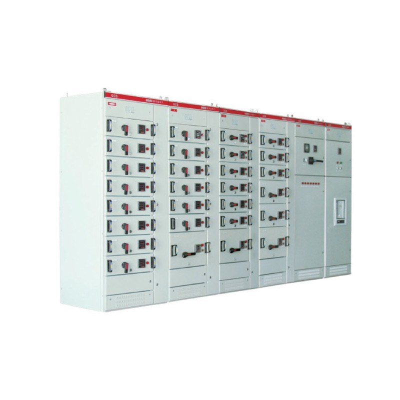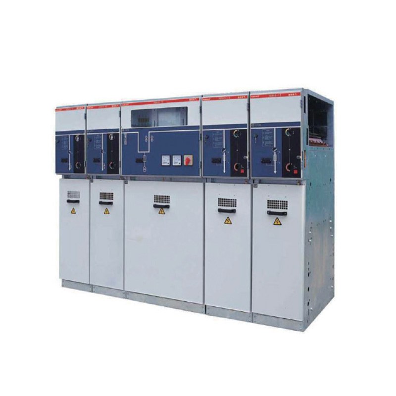
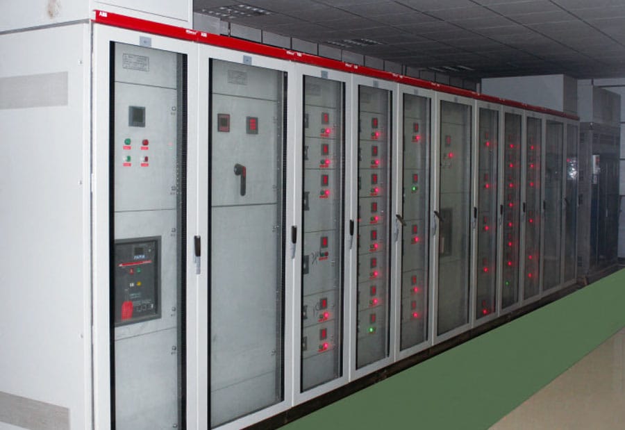
Table of Contents
Introduction
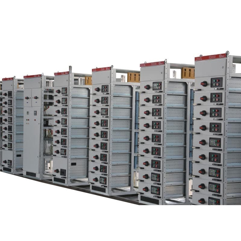
Medium Voltage Switchgear is a central part of many electrical distribution systems because it brings switching, protection, isolation, measurement, and feeder control together at the point where medium-voltage power needs to be received and distributed. Its job is not simply to carry electrical current. It must also help the system respond predictably when circuits are switched, equipment is maintained, loads change, or faults occur.
For project teams, this makes switchgear selection more complex than comparing rated voltage and current. The incoming power arrangement, transformer capacity, feeder quantity, short-circuit level, relay protection, cable routing, operating sequence, installation environment, maintenance access, and future expansion all affect the final configuration. A cabinet that satisfies basic ratings may still be poorly suited to the system if these relationships are not considered together.
This guide explains what Medium Voltage Switchgear does, how its major functions interact, what specifications deserve the most attention, and how to evaluate a switchgear lineup as part of the complete electrical distribution system rather than as a collection of independent panels.
What Is Medium Voltage Switchgear?
Medium Voltage Switchgear is electrical equipment used to switch, control, protect, and isolate medium-voltage circuits. The broader concept of switchgear includes combinations of switching and protective devices used to manage electrical power systems, but medium-voltage installations require particular attention to insulation, fault interruption, operating safety, and protection coordination.
In a typical distribution system, Medium Voltage Switchgear can sit between the incoming power source and transformers or other outgoing feeders. Different panels within the lineup may perform different functions, such as receiving incoming power, supplying transformers, feeding other distribution sections, providing measurement, or supporting busbar sectionalizing.
This means switchgear should not be viewed as one cabinet performing one task. It is better understood as an organized electrical system in which several panels work together according to the single-line diagram and operating philosophy of the project.
A well-planned lineup makes the electrical path easier to understand. Operators can see where power enters, how it is distributed, which devices protect each feeder, and how individual sections can be isolated when inspection or maintenance is required.
How Medium Voltage Switchgear Works in a Distribution System
The basic operating logic begins with an incoming feeder. Electrical power enters the switchgear and reaches the busbar system through the appropriate switching and protective arrangement. From there, the busbars distribute power to outgoing feeders, which may supply transformers, additional switchgear sections, large electrical loads, or other parts of the medium-voltage network.
Under normal conditions, circuit breakers or other switching devices remain in the operating positions required by the system. Measurement and protection equipment continuously provide information about current, voltage, and abnormal electrical conditions where those functions are included.
When a fault occurs, the protection system evaluates electrical signals and determines whether a circuit should be disconnected. The switching device must then interrupt the faulted circuit according to the protection logic. A well-coordinated system aims to isolate the affected section without unnecessarily interrupting healthy parts of the network.
This is why the switchgear and protection system must be designed together. The circuit breaker provides interruption capability, but it does not independently determine the entire protection strategy. Current transformers, voltage measurement, relays, control circuits, interlocking logic, and upstream and downstream protective devices all contribute to how the system responds.
Understand the Main Parts of Medium Voltage Switchgear
Although switchgear configurations vary, the important components generally perform several recurring functions. The busbar carries and distributes power within the lineup, while circuit breakers or other switching devices control individual circuits. Cable compartments provide the physical and electrical interface with incoming and outgoing conductors, and protection and control sections support measurement, relay functions, indication, and operational control.
The important point is not simply knowing the component names. Their physical and electrical relationship matters.
For example, the position of the cable compartment affects termination access. The location and arrangement of the circuit breaker influence operating and maintenance procedures. Busbar design affects how panels connect to form a lineup. Protection components need accurate electrical inputs if they are expected to identify abnormal conditions correctly.
Interlocking is another important part of the overall design. Medium-voltage equipment requires operating sequences that reduce the possibility of inappropriate switching actions. Mechanical and electrical interlocking should therefore reflect the actual operating philosophy instead of being treated as an accessory added after the main cabinet arrangement is defined.
The quality of a switchgear design can often be judged by how clearly these functions are separated while still working as one coordinated system.
Rated Voltage Is Only the Starting Point
Rated voltage is usually the first specification considered when choosing Medium Voltage Switchgear, but voltage alone does not define whether the equipment is suitable.
Rated current, busbar capacity, feeder current, short-time withstand capability, insulation requirements, circuit-breaker characteristics, and the expected short-circuit level all influence the specification. These values should be derived from the actual electrical network rather than copied from a previous project with similar-looking equipment.
This is particularly important because normal current and fault current describe very different operating conditions. Normal current represents the load the switchgear must carry during regular operation, while fault current represents the much higher electrical stress that may occur for a short period during an abnormal event.
A switchgear lineup therefore needs to satisfy both continuous operating requirements and defined fault conditions. Selecting equipment only from normal load current leaves an important part of the electrical design unanswered.
The same principle applies to future expansion. If a project is expected to add transformers or outgoing feeders later, that development may influence busbar loading, incoming capacity, protection studies, and the physical panel sequence. Future planning should therefore be connected to a realistic system development scenario.
Short-Circuit Ratings Must Match the Actual Network
Short-circuit performance is one of the most important parts of Medium Voltage Switchgear selection because the available fault current depends on the electrical system upstream of the cabinet.
Transformer capacity and impedance, network configuration, cable characteristics, generator contribution where applicable, and other sources can influence the fault level. As a result, two switchgear lineups carrying similar normal loads may still require different short-circuit capabilities.
The fault study should therefore be completed before the final switchgear specification is confirmed. Circuit breakers must be capable of interrupting the applicable fault current, while busbars and associated current-carrying structures need suitable withstand performance for the system conditions they may experience.
This becomes especially important when an upstream transformer or network arrangement changes during the project. Increasing transformer capacity may appear unrelated to the switchgear specification, yet it can change the available short-circuit current and require the switchgear and protection study to be reviewed.
A useful engineering habit is therefore to ask what other specifications are affected whenever a major part of the electrical system changes.
Protection Coordination Matters as Much as Breaker Capability
A circuit breaker capable of interrupting the required fault current is essential, but fault interruption alone does not create a well-coordinated protection system.
Protection coordination determines which device should operate for a particular abnormal condition and how different levels of the distribution system should interact. Ideally, a fault on an outgoing circuit should be cleared by the protective device responsible for that section, while upstream equipment remains in service where the system design permits.
If protection settings are poorly coordinated, a relatively small downstream fault can result in a larger interruption than necessary. On the other hand, protection that responds too slowly or incorrectly may allow abnormal electrical stress to remain for longer than intended.
For this reason, the transformer, incoming feeder, bus coupler where used, outgoing feeders, downstream equipment, and protection relays should be reviewed as one electrical hierarchy.
DFDL’s medium-voltage distribution system similarly organizes incoming power, feeder protection, transformer-side distribution, cable access, and future feeders around the complete system rather than treating each cabinet as an isolated selection.
Panel Arrangement Should Follow the Single-Line Diagram
Switchgear lineups should grow from the project’s single-line diagram. The drawing identifies how power enters, where it is measured, how busbars are arranged, which circuits feed transformers or other loads, and how sections of the network may be connected or isolated.
Once this structure is clear, the panel sequence can be developed logically. Incoming panels, metering sections, outgoing feeders, transformer feeders, sectionalizing functions, and reserved positions should follow the way the system is expected to operate.
Problems often arise when equipment is selected panel by panel before the complete lineup is understood. The result may be technically usable individual cabinets but an inefficient overall arrangement with difficult cable routes, unclear operating sequences, or unnecessary changes during installation.
Panel order also influences physical layout. Cable-entry positions, busbar connections, room dimensions, front and rear access requirements, and maintenance clearances can all depend on how the lineup is arranged.
For this reason, electrical and physical design should develop together rather than treating the switchgear room as a space that is finalized after equipment selection.
Cable Entry and Termination Need Early Planning
Cable routing is one of the most practical parts of Medium Voltage Switchgear design, yet it is frequently addressed too late.
Incoming and outgoing cables need enough space for routing, bending, support, identification, termination, inspection, and future maintenance. The direction of cable entry should therefore be confirmed before the cabinet layout and electrical room are finalized.
A switchgear panel may fit comfortably within the available floor area while the cable compartment remains difficult to access because trench positions, cable approach angles, or termination requirements were not considered early enough.
Cable routing can also influence panel order. If several outgoing feeders leave in different directions, arranging cabinets only according to the electrical drawing without considering the physical route may create unnecessary cable crossings or difficult installation work.
The goal should be to make the physical cable path as understandable as the electrical single-line diagram. When the two correspond clearly, installation, identification, inspection, and future modifications become easier.
Medium Voltage Switchgear vs Ring Main Unit
Medium Voltage Switchgear and a Ring Main Unit can both perform medium-voltage switching and protection functions, but they are not automatically interchangeable.
A full switchgear lineup is often useful where the project requires structured incoming and outgoing feeders, detailed protection, metering, multiple circuit breakers, sectionalizing, clear panel separation, or broader expansion capability. A Ring Main Unit is generally associated with compact distribution nodes and ring-network arrangements where space efficiency and feeder switching are important.
The right choice should therefore come from system architecture rather than product preference.
If the network requires several protected feeders, detailed relay functions, extensive metering, or a large structured lineup, conventional Medium Voltage Switchgear may provide a clearer system arrangement. Where the node is compact and the switching functions are more concentrated, an RMU configuration may be more appropriate.
Some projects can use both. Medium-voltage switchgear may serve the main distribution point while RMUs support downstream ring-network nodes. In this arrangement, both equipment types need to follow the same protection, cable-routing, and operating philosophy.
The question should not be which technology is better overall. It should be which equipment structure matches the function of each point in the network.
Installation Environment Affects Switchgear Configuration
Electrical ratings tell only part of the story. Medium Voltage Switchgear must also fit the physical and environmental conditions of the installation.
Ambient temperature, humidity, dust, contamination, ventilation, altitude where relevant to the project requirements, and available room space can all influence equipment configuration. Indoor equipment still requires environmental evaluation because electrical rooms can experience heat, dust, restricted airflow, or other conditions that affect long-term operation.
Moisture and condensation deserve particular attention. Even when direct water exposure is not expected, changing temperature and humidity can affect the internal environment. Cabinet sealing, room ventilation, heating or moisture-control measures where required, and maintenance practices should therefore form part of the overall installation strategy.
Accessibility is equally important. Operators need appropriate space to perform switching, while maintenance personnel need practical access for inspection, cable work, testing, and component servicing.
A technically suitable switchgear lineup becomes harder to operate safely and efficiently when the room layout provides inadequate access. Equipment configuration and site planning should therefore be reviewed together before final drawings are approved.
Withdrawable and Fixed Designs Require Different Thinking
Switchgear construction can influence how operators and maintenance teams interact with the equipment. Withdrawable designs allow certain functional units, such as circuit breakers, to move between defined operating positions according to the equipment arrangement, while fixed designs use a different approach to mounting and connection.
Neither arrangement should be chosen from appearance alone. The decision should reflect maintenance philosophy, operating requirements, feeder criticality, space constraints, and the type of system being built.
A withdrawable arrangement can make it easier to separate certain functional elements for inspection or service, but it also depends on mechanical positioning, interlocking, shutters, secondary connections, and other parts remaining in appropriate condition.
Fixed equipment may use a simpler physical arrangement but still requires suitable isolation, access, testing procedures, and maintenance planning.
The better design is the one that fits the operating model. Project teams should consider how frequently equipment may need inspection, how feeder outages will be managed, what maintenance resources are available, and how the switchgear will be operated over its service life.
Digital Monitoring Should Solve an Operational Problem
Modern Medium Voltage Switchgear can incorporate increasing amounts of monitoring and communication capability, but adding digital features is useful only when the information supports an actual operational requirement.
Current, voltage, breaker status, protection events, temperature information, and communication interfaces can help operators understand what is happening inside the distribution system. For facilities with multiple substations or distributed electrical rooms, remote information can also reduce the time needed to identify which feeder or protection device has operated.
However, the design should begin by identifying what information is needed and how it will be used. Monitoring that produces data without a defined maintenance or operational response adds complexity without necessarily improving reliability.
A practical approach is to connect each monitoring function with a decision. If temperature information is collected, define what trend would trigger inspection. If breaker operating counts are recorded, determine how they support maintenance planning. If remote status is needed, identify who uses it and what action follows an abnormal indication.
Digital switchgear becomes more valuable when data supports clear operational decisions rather than simply increasing the number of available measurements.
Practical Medium Voltage Switchgear Selection Table
The following table summarizes the main areas that should be confirmed before a Medium Voltage Switchgear lineup is finalized.
| Selection Area | What Should Be Confirmed | Why It Matters |
|---|---|---|
| System voltage | Network voltage and insulation requirements | Establishes electrical compatibility |
| Rated current | Incoming, busbar and feeder loading | Supports normal operating demand |
| Short-circuit level | Calculated fault current and duration | Determines breaker and withstand requirements |
| Protection | Relay functions and coordination logic | Supports selective fault isolation |
| Panel sequence | Incoming, metering, outgoing and sectionalizing functions | Creates a logical operating arrangement |
| Cable system | Entry direction, quantity and termination space | Prevents installation and maintenance conflicts |
| Construction | Fixed or withdrawable arrangement | Affects operation and service strategy |
| Environment | Temperature, humidity, contamination and room conditions | Influences long-term equipment performance |
| Interlocking | Mechanical and electrical operating logic | Supports controlled switching sequences |
| Monitoring | Measurements, status, alarms and communications | Provides useful operational information |
| Maintenance | Access, inspection, testing and documentation | Supports long-term serviceability |
| Expansion | Probable additional feeders and future load changes | Reduces disruptive redesign later |
The table should be used as a coordinated review rather than as a collection of independent specifications. Changing one item can affect several others. Additional feeders may alter busbar loading and room length, while a transformer change may affect fault current and protection settings.
A strong switchgear specification therefore remains connected to the full electrical system throughout the design process.
Common Medium Voltage Switchgear Selection Mistakes
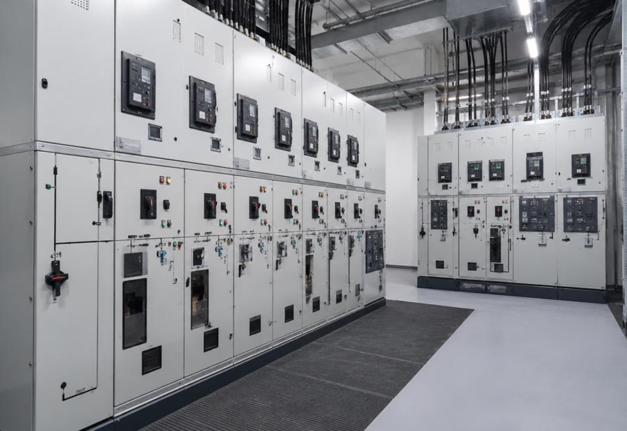
One common mistake is choosing Medium Voltage Switchgear primarily from rated voltage and current. These specifications are essential, but they do not describe fault level, protection coordination, feeder functions, cable routing, operating sequence, or maintenance conditions.
Another mistake is finalizing panel quantity before the single-line diagram and network operating philosophy are stable. This can lead to later cabinet additions, altered busbar arrangements, or unnecessarily complicated cable routes.
Short-circuit calculations are also sometimes treated as a final verification step. In reality, fault level should influence switchgear selection from the beginning because it affects breaker capability, busbar withstand requirements, and the overall protection strategy.
Physical layout creates another group of avoidable problems. A switchgear lineup may fit the electrical room while leaving inadequate space for cable termination, operating access, inspection, or future panel additions.
Finally, future expansion is often reduced to leaving an empty space at the end of the lineup. Real expansion planning should also consider busbar capacity, incoming capacity, protection, cable routes, room dimensions, and whether the future feeder requirement is actually understood.
What Information Should Be Prepared Before Configuration?
The quality of a Medium Voltage Switchgear specification depends heavily on the quality of the project information provided before configuration begins.
The single-line diagram is usually the most important starting document because it establishes how incoming power, busbars, transformers, feeders, protection, and downstream distribution are related. A load schedule adds information about current requirements, while a protection study clarifies fault levels and the intended response to abnormal conditions.
Physical information is equally important. Electrical-room dimensions, cable trenches, entry direction, operating clearances, access routes, environmental conditions, and future expansion areas all influence the final arrangement.
Project teams should also identify the required measurement, relay, interlocking, local control, remote monitoring, and communication functions before the panel layout is finalized. Adding these requirements late can affect internal space and wiring architecture.
The aim is not to create unnecessary documentation. It is to remove assumptions early enough that electrical and mechanical design decisions can be coordinated before equipment is built.
DFDL’s power distribution equipment portfolio brings medium- and low-voltage distribution equipment together for project-side system matching, which is particularly useful when switchgear needs to coordinate with cables, ring network equipment, and downstream distribution.
A Three-Layer Method for Evaluating Medium Voltage Switchgear
A practical way to evaluate Medium Voltage Switchgear is to divide the project into electrical, physical, and operational layers.
The electrical layer asks whether the switchgear matches the voltage, current, short-circuit level, feeder arrangement, transformer interfaces, protection requirements, and expected system development. If this layer is incomplete, the equipment may not behave correctly within the network even if the physical cabinet construction is suitable.
The physical layer asks whether the switchgear can actually be installed and maintained in the available space. Cable entry, panel dimensions, busbar arrangement, access, environmental conditions, ventilation, and expansion space belong to this layer.
The operational layer asks how people will use the equipment. Switching sequences, interlocking, indication, protection events, inspection procedures, maintenance access, documentation, and monitoring should all make sense for the organization responsible for the system.
A suitable Medium Voltage Switchgear design should perform well in all three layers. Strong electrical ratings cannot compensate for poor installation access, and an excellent mechanical layout cannot compensate for weak protection coordination.
Conclusion
Medium Voltage Switchgear should be selected as part of a complete electrical distribution system rather than as a cabinet defined only by voltage and current. Its performance depends on how switching devices, busbars, protection relays, cable interfaces, interlocking, measurement, panel arrangement, and operating procedures work together.
A strong design starts with the single-line diagram and confirms the real network conditions before panel configuration begins. Rated current must match normal operation, while short-circuit capability must match calculated fault conditions. Protection should coordinate across different distribution levels, cable routes should be planned before the room layout is finalized, and the equipment should provide practical access for operation and maintenance.
Long-term requirements matter as well. Future feeders, changes in transformer capacity, monitoring requirements, and maintenance strategy can influence decisions that are much easier to make during initial design than after installation.
When electrical, physical, and operational requirements are evaluated together, Medium Voltage Switchgear becomes more than a switching cabinet. It becomes an organized distribution platform that helps the wider power system remain controllable, maintainable, and adaptable over time.
FAQ
What is Medium Voltage Switchgear used for?
Medium Voltage Switchgear is used to receive, switch, protect, isolate, and distribute medium-voltage electrical circuits. Depending on the system, it can manage incoming power, transformer feeders, outgoing circuits, metering, protection, and busbar sections within a coordinated distribution lineup.
How do I choose the correct Medium Voltage Switchgear?
Start with the system voltage, rated current, calculated short-circuit level, feeder quantity, protection philosophy, transformer arrangement, cable routes, installation environment, and maintenance requirements. The final configuration should follow the single-line diagram rather than cabinet size alone.
Why is short-circuit rating important for Medium Voltage Switchgear?
During a fault, current can be much higher than normal load current. The circuit breaker must be capable of interrupting the applicable fault level, while busbars and related equipment must withstand defined fault conditions. The rating should therefore come from the actual system study.
What is the difference between Medium Voltage Switchgear and an RMU?
Both can perform medium-voltage switching and protection, but they usually serve different system structures. Medium Voltage Switchgear is often used for structured multi-panel distribution and detailed protection, while RMUs are commonly used at compact ring-network and feeder distribution nodes.
What information is needed before specifying Medium Voltage Switchgear?
Useful information includes the single-line diagram, system voltage, load and feeder data, transformer information, short-circuit level, relay requirements, cable entry, room layout, environmental conditions, monitoring needs, operating philosophy, and realistic future expansion requirements.
Need Help Choosing the Right Medium Voltage Switchgear?
If you’re unsure which Medium Voltage Switchgear configuration best matches your feeder arrangement, fault level, transformer system, cable layout, protection requirements, or future expansion needs, our technical team can help review the project as a complete distribution system. Share your electrical drawings and operating requirements to develop a practical switchgear configuration built around reliable operation and long-term maintainability.