Table of Contents
Introduction
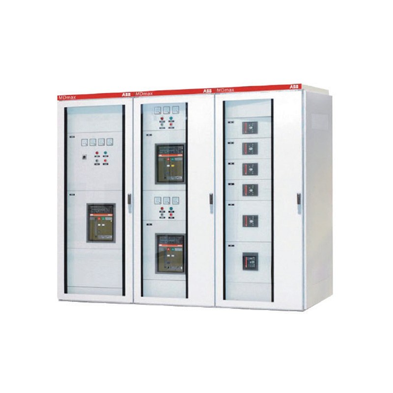
Choosing Low Voltage Switchgear is not simply a matter of matching voltage and rated current. In a real electrical distribution project, switchgear has to receive power, divide it among different feeders, coordinate protective devices, support control and metering functions, provide practical access for maintenance, and remain suitable when loads or operating requirements change.
Two switchgear lineups with similar headline ratings can perform very differently once installed. One may have clear feeder organization, practical cable access, suitable protection coordination, and reasonable expansion capability, while another becomes crowded or difficult to maintain because important project conditions were not considered early enough.
A useful low voltage switchgear selection guide therefore needs to look beyond product specifications. The correct configuration depends on the load profile, incoming supply, feeder structure, fault conditions, fixed or withdrawable arrangement, cable requirements, thermal environment, monitoring needs, maintenance strategy, and expected system development. The following eight factors provide a practical way to evaluate these requirements as one coordinated electrical system.
Factor 1: Start with the Actual Role of the Low Voltage Switchgear
Before selecting cabinet dimensions or breaker types, define exactly what the Low Voltage Switchgear is expected to do in the electrical system. Switchgear is broadly used to control, protect, and isolate electrical equipment, as explained in the general concept of switchgear, but the actual function of an individual low-voltage lineup can vary significantly from one project to another.
Some installations use Low Voltage Switchgear mainly for centralized power distribution. The incoming section receives power and distributes it through the busbar to several outgoing feeders. Other systems combine distribution with motor-control functions, metering, compensation interfaces, auxiliary circuits, or process-related control.
This functional definition determines the rest of the design. A lineup serving several large outgoing feeders has different requirements from one containing many smaller motor-control units. Likewise, a system that needs frequent feeder maintenance may benefit from a different internal structure than one where circuits rarely change.
The most reliable starting point is therefore the single-line diagram. It should show where power enters, which loads or downstream cabinets are supplied, how feeders are grouped, where protection sits, and whether the system contains multiple sections or bus connections. Once this architecture is clear, the switchgear configuration can follow the actual electrical function instead of forcing the project into a predefined cabinet layout.
Factor 2: Calculate Load Demand Instead of Using Connected Load Alone
The total installed load is useful information, but it should not automatically become the switchgear design current. Real operating demand depends on which loads run simultaneously, how long they operate, and what happens during peak conditions.
A facility may contain motors, pumps, ventilation equipment, lighting, heating systems, automation equipment, electronic loads, process machinery, and auxiliary systems. Their combined nameplate ratings can be significantly different from the current that actually flows through the switchgear during normal operation.
At the same time, using average demand alone can underestimate important operating conditions. Large motors may create higher current during starting, production equipment may operate in groups during certain periods, and future equipment can increase feeder loading after the original system has been commissioned.
Low Voltage Switchgear selection should therefore begin with a realistic load schedule. The incoming section, main busbar, outgoing feeders, and protective devices should be evaluated against normal operating demand, expected peak demand, load variation, and clearly identified future expansion.
This is particularly important because the load profile also influences thermal performance. Two lineups with the same rated current may behave differently if one operates at a relatively stable load while the other experiences frequent changes and high simultaneous demand.
The goal is not simply to prove that the switchgear has enough current capacity. It is to understand where and when current flows through the system so the electrical and physical configuration reflects actual operation.
Factor 3: Confirm Rated Current and Busbar Capacity Together
Rated current should be evaluated at several levels rather than treated as one switchgear number.
The incoming circuit has its own current requirement. The main busbar must support the current that can flow through the relevant section of the lineup. Individual outgoing feeders need ratings that correspond to their loads and conductors. Where multiple sections or bus couplers are used, the operating arrangement can also influence how much current different parts of the busbar may carry.
This makes busbar capacity an important part of Low Voltage Switchgear selection. A system may have sufficient outgoing feeder capacity while the main distribution path becomes the limiting factor. Conversely, selecting a very high busbar rating without a realistic requirement does not automatically create a better system.
Future expansion should be considered here as well. If additional feeders are expected, the project should ask whether the incoming supply, transformer, main busbar, downstream cables, and surrounding equipment can support them. An unused cabinet position does not guarantee that useful electrical capacity remains available.
A practical approach is to identify the present load, probable future load, and expected operating arrangement before fixing the incoming and busbar ratings. This produces a switchgear configuration based on realistic system development instead of arbitrary oversizing.
Factor 4: Check Short-Circuit Conditions and Protection Coordination
Normal operating current describes what the Low Voltage Switchgear carries every day. Short-circuit current describes the much more severe electrical condition that may occur during a fault.
The available fault current depends on the upstream system. Transformer capacity and impedance, conductor characteristics, distribution arrangement, and the electrical distance between the transformer and switchgear can all influence the fault level at the installation point.
Protective devices therefore need to be selected according to more than their normal current rating. They must also be suitable for the fault conditions of the actual system, while the switchgear’s busbars and current-carrying structures must have appropriate withstand characteristics.
Protection coordination is equally important. The objective is not merely to ensure that something trips during a fault. A well-organized system should isolate the affected circuit as locally as practical so healthy sections can remain available where the electrical design permits.
Consider an outgoing feeder with a fault downstream. If the incoming protective device operates before the feeder device, the entire lineup may lose power even though the problem exists on only one circuit. This does not necessarily indicate that either breaker is defective. It may indicate that the protection relationship was not coordinated properly.
That is why Low Voltage Switchgear should be planned together with the complete low-voltage distribution and control system. Transformer characteristics, incoming devices, outgoing breakers, cables, load behavior, and downstream protection all influence how the system responds to abnormal conditions.
Factor 5: Decide Between Fixed and Withdrawable Configurations
One of the most important structural choices is whether the project requires fixed or withdrawable Low Voltage Switchgear.
A fixed configuration keeps major functional devices installed in their defined positions within the cabinet. This can provide a straightforward internal arrangement for applications where feeder configuration is relatively stable and the maintenance strategy does not require frequent removal of functional units.
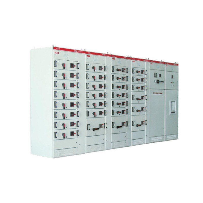
Withdrawable switchgear uses removable functional units or drawers that can be moved through defined operating positions according to the equipment design. This arrangement can be useful where individual feeders or motor-control circuits need clearer functional separation, where maintenance planning values modularity, or where replacement and circuit management need to be organized around individual units.
The correct choice is therefore not determined by which design appears more advanced. It depends on how the electrical system will actually be operated and maintained.
If a project contains many critical feeders, process loads, or motor-control circuits that may require independent servicing, a withdrawable arrangement can provide practical advantages. If the distribution structure is relatively simple and circuits rarely change, a fixed configuration may meet the operational requirements effectively.
Maintenance capability should also be considered. Withdrawable equipment includes mechanical positioning, interlocking, connection mechanisms, and other moving parts that need to remain in suitable condition. The benefits of modularity are most valuable when the maintenance team understands how the equipment is designed to be operated and inspected.
The final decision should therefore match operating frequency, maintenance philosophy, feeder criticality, available space, and the expected lifecycle of the electrical system.
Factor 6: Plan Feeder Quantity and Functional Separation Early
Low Voltage Switchgear often becomes difficult to modify when feeder quantity and cabinet structure are finalized too early.
The number of outgoing feeders is important, but feeder quantity alone does not describe the required lineup. Each feeder can have different current ratings, conductor sizes, protection requirements, control functions, metering needs, and maintenance importance.
A good layout groups functions logically. Incoming power should be easy to identify, outgoing feeders should follow a clear sequence, motor-control functions should remain understandable, and metering or compensation interfaces should not create unnecessary wiring complexity.
Functional separation can also improve troubleshooting. When a technician needs to investigate one circuit, the location and purpose of that feeder should be clear from the physical arrangement and documentation.
This is especially valuable in industrial systems where loads may be grouped by process area, production line, equipment type, or building section. A clear layout makes later modifications easier because new circuits can be added within an existing distribution logic rather than placed wherever physical space happens to remain.
Future feeders should therefore be planned with realistic intent. Reserving several unused positions can be useful when expansion is expected, but excessive spare sections without a defined purpose can increase cabinet length and complexity without improving the actual system.
Low Voltage Switchgear works best when the physical lineup reflects the electrical logic of the facility.
Factor 7: Give Cable Routing as Much Attention as Cabinet Space
Cable installation is one of the areas most likely to reveal weaknesses in an otherwise acceptable switchgear design.
Electrical diagrams represent conductors as simple lines, but real cables require space for entry, bending, support, identification, termination, and inspection. Larger feeders can need substantial room even when the associated circuit breaker occupies relatively little cabinet space.
Before switchgear dimensions are finalized, the project should confirm cable entry direction, approximate conductor sizes, feeder quantity, termination positions, and the relationship between cable trenches or routing systems and the cabinet lineup.
If cables enter from below, the termination arrangement needs to align with trench positions and available bending space. If alternative routing is required, the internal design needs to support that method without creating congestion around breakers or busbars.
Maintenance access should be part of the same discussion. Technicians may eventually need to inspect terminals, test conductors, identify circuits, or carry out modifications. A cable compartment that is technically large enough for installation may still be difficult to maintain if conductors are densely routed across one another.
This is why compact Low Voltage Switchgear should not be evaluated only by how little floor space it occupies. Space efficiency has real value, but excessive density can make installation, heat management, and maintenance more difficult.
A well-planned system uses cabinet space efficiently while keeping the electrical path visible and accessible.
Factor 8: Evaluate Thermal Conditions, Environment, and Maintenance
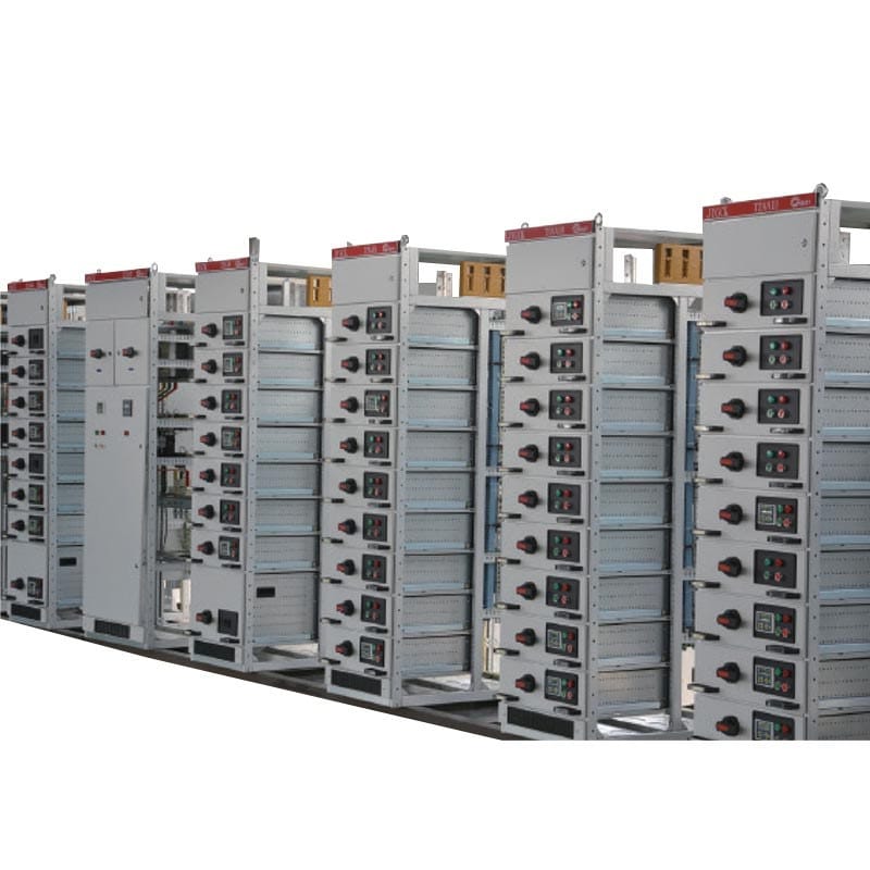
Heat is a normal part of electrical operation. Busbars, conductors, connections, circuit breakers, control devices, and other components all generate losses that become heat. The internal temperature of Low Voltage Switchgear therefore depends on both electrical loading and physical arrangement.
High component density, limited airflow, elevated ambient temperature, contamination, and sustained loading can all make thermal management more demanding. This is why switchgear that physically accommodates every component may still require further evaluation if the arrangement leaves little room for heat dissipation.
The installation environment matters as well. A clean, controlled electrical room creates different operating conditions from a location affected by dust, moisture, heat, or process-related contamination. Enclosure structure and ventilation strategy should reflect the actual environment rather than a generic indoor designation.
Maintenance access deserves equal attention. The lineup should provide practical routes for inspection of breakers, connections, cable terminations, indication devices, and other important components. Clear labeling and drawings should allow technicians to understand how the physical cabinet corresponds with the electrical documentation.
This is also where long-term reliability becomes part of the selection process. A switchgear lineup can remain in service while the facility around it changes. New equipment may increase the load, circuits may be reassigned, and additional monitoring may be introduced. A maintainable system makes these changes easier to understand and manage.
For this reason, switchgear selection should consider not only what the equipment needs to do when commissioned but also how easy it will be to inspect, diagnose, and modify later.
Low Voltage Switchgear Selection Checklist
The following table summarizes the main project information that should be reviewed before a Low Voltage Switchgear configuration is finalized.
| Selection Factor | What to Confirm | Why It Matters |
|---|---|---|
| System role | Incoming, distribution, motor control or mixed functions | Defines the overall cabinet architecture |
| Load profile | Normal, peak, intermittent and future loads | Establishes realistic current requirements |
| Rated current | Incoming, busbar and individual feeder currents | Prevents current capacity from becoming a system bottleneck |
| Fault conditions | Available short-circuit current and protection arrangement | Supports suitable interruption and withstand performance |
| Cabinet type | Fixed or withdrawable configuration | Affects maintenance, operation and functional organization |
| Feeder structure | Quantity, load type, grouping and expansion | Determines cabinet sequence and internal layout |
| Cable routing | Entry direction, cable size and termination requirements | Prevents installation congestion |
| Thermal conditions | Load density, ambient environment and ventilation | Supports stable long-term operation |
| Monitoring | Metering, status and control requirements | Improves operational visibility where needed |
| Maintenance | Inspection, access, labeling and documentation | Makes future service and troubleshooting easier |
| Expansion | Probable additional feeders and loads | Helps avoid disruptive redesign |
The value of this checklist comes from using the factors together. Increasing transformer capacity, for example, may affect fault current. Adding feeders may increase busbar loading and cabinet length. A more compact layout may change cable and thermal conditions. The switchgear therefore needs to be evaluated as a connected system rather than a collection of separate specifications.
How to Compare Different Low Voltage Switchgear Configurations
When several Low Voltage Switchgear options meet the basic voltage requirement, the comparison should move beyond the number of cabinets and breaker ratings.
First compare the electrical architecture. Does each option provide an incoming arrangement that matches the actual source? Are feeder ratings suitable for the load schedule? Does the main busbar support both present operation and realistic expansion? Are protection devices coordinated with the system fault level?
Next compare the physical arrangement. One lineup may be shorter but place more components within each section. Another may occupy more floor space while offering clearer cable routing and maintenance access. Neither is automatically better. The correct choice depends on the physical limitations and operating requirements of the project.
The third comparison should focus on lifecycle operation. How easily can a feeder be identified? How practical is inspection? Can additional circuits be integrated without disrupting the existing layout? Are drawings and labels easy to maintain? Does the configuration fit the skills and procedures of the team responsible for the electrical system?
This approach prevents product comparison from becoming a simple specification-sheet exercise. The most suitable switchgear is the configuration that fits the electrical, physical, and operational requirements at the same time.
How Load Type Changes Low Voltage Switchgear Selection
The type of connected load can influence switchgear configuration even when total current remains similar.
Motor loads, for example, can introduce starting conditions and control requirements that differ from stable building-service loads. A system with many motors may require more attention to feeder organization, switching frequency, control functions, and protection settings.
Electronic and power-conversion loads can introduce different operating characteristics. Their current waveform, load variation, and interaction with the wider distribution system can affect how the project approaches monitoring, thermal conditions, and power-quality planning.
Lighting and auxiliary loads may require many smaller outgoing circuits rather than a limited number of large feeders. In this case, the challenge may be circuit organization and identification rather than main feeder capacity.
Mixed-load systems are particularly important because they can combine all these requirements within one electrical room. A practical design may separate feeder groups according to operating function rather than simply arranging breakers in descending current order.
Understanding load behavior therefore helps determine not only ratings but also how the Low Voltage Switchgear should be organized internally.
When Does Withdrawable Low Voltage Switchgear Make Sense?
Withdrawable Low Voltage Switchgear can be especially useful where the operating system benefits from modular functional units and clearer separation between circuits.
Industrial process loads are one example. When different feeders or motor-control circuits support independent sections of an operating facility, maintenance teams may value the ability to manage individual functional units without treating the entire lineup as one fixed assembly.
Withdrawable arrangements can also support future reconfiguration when the equipment design and available capacity allow it. Standardized functional positions can make the internal architecture easier to understand compared with a system that has accumulated many unrelated modifications over time.
However, modularity should not be selected simply because future expansion is possible. The incoming system, busbar capacity, protection, conductor routes, and physical cabinet space still need to support any additional load.
The wider power distribution equipment range includes several low-voltage switchgear configurations alongside distribution cabinets and supporting electrical equipment, making it useful to evaluate switchgear within the surrounding power distribution architecture rather than as a standalone cabinet.
Common Low Voltage Switchgear Selection Mistakes
One common mistake is selecting switchgear from rated current alone. A lineup can have adequate continuous current capacity while still being poorly matched to fault conditions, cable requirements, feeder functions, or the maintenance strategy.
Another mistake is treating every spare cabinet position as future capacity. Physical space and electrical capacity are different. The transformer, incoming feeder, busbars, conductors, thermal conditions, and protection system must all support additional load before expansion is practical.
Cable space is also frequently underestimated. The protective devices may fit comfortably in the selected sections while the conductors require much more room than expected for termination and routing. These problems are easier to prevent during design than to solve during installation.
Choosing fixed or withdrawable construction without considering maintenance is another weakness. The cabinet structure should support the way technicians actually operate and service the system rather than being selected from a generic preference.
Finally, project teams sometimes finalize the switchgear before the load schedule and single-line diagram are stable. This reverses the design process. Low Voltage Switchgear should develop from the system requirements, not become a fixed constraint that later electrical decisions must work around.
A Practical Four-Stage Selection Method
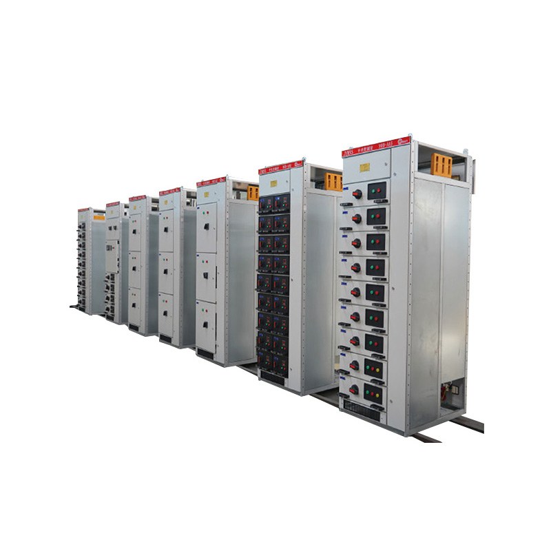
A useful way to simplify Low Voltage Switchgear selection is to divide the decision into four stages.
The first stage is electrical definition. Confirm the supply arrangement, transformer interface, system voltage, load profile, incoming current, feeder quantity, short-circuit conditions, and protection philosophy. These factors establish what the switchgear must do electrically.
The second stage is configuration planning. Decide whether fixed or withdrawable architecture makes more sense, organize feeder groups, identify metering and control functions, and determine what future circuits are realistically expected.
The third stage is physical verification. Review cabinet dimensions, cable-entry routes, termination space, room layout, ventilation, access, and environmental conditions. This stage confirms that the electrical design can be installed and maintained in the actual site.
The final stage is lifecycle review. Consider inspection procedures, circuit identification, future expansion, documentation, monitoring, and the likely operating changes that may occur over the service life of the equipment.
Using these four stages helps prevent a common selection problem: approving a technically acceptable switchgear specification that does not fit the way the complete electrical system will actually be installed and operated.
Conclusion
A reliable low voltage switchgear selection guide should connect electrical ratings with real operating conditions. Rated voltage and current are necessary starting points, but they do not describe the complete requirements of a working distribution system.
The selection process should begin with the role of the switchgear and a realistic load profile. Incoming and busbar capacity need to support both present demand and justified future development, while fault-current conditions and protection coordination must be evaluated within the complete electrical network. Fixed and withdrawable configurations should be selected according to operational and maintenance needs rather than appearance or general preference.
Feeder organization, cable routing, thermal conditions, installation environment, monitoring, and maintenance access are equally important. These physical and lifecycle considerations determine whether the switchgear remains clear and practical after years of operation and modification.
The strongest Low Voltage Switchgear configuration is therefore not simply the one with the highest ratings or the greatest number of features. It is the one that matches the actual electrical system, provides a clear distribution architecture, supports practical maintenance, and leaves realistic room for the way the project is expected to develop.
FAQ
What is Low Voltage Switchgear?
Low Voltage Switchgear is electrical equipment used to distribute, switch, protect, control, and isolate low-voltage circuits. A lineup can include incoming sections, busbars, outgoing feeders, breakers, motor-control functions, metering, and other devices depending on the electrical system.
How do I choose the right Low Voltage Switchgear?
Start with system voltage, actual load demand, incoming current, busbar capacity, feeder quantity, short-circuit level, protection requirements, cable arrangement, installation environment, maintenance strategy, and future expansion before choosing the cabinet configuration.
Should I choose fixed or withdrawable Low Voltage Switchgear?
The choice depends on feeder functions, maintenance needs, operating frequency, system criticality, available space, and future configuration requirements. Withdrawable designs can support modular circuit management, while fixed designs may suit systems with more stable distribution arrangements.
Why is short-circuit current important for Low Voltage Switchgear?
Short-circuit current determines the electrical stress that breakers, busbars, and other current-carrying components may experience during a fault. The switchgear and its protective devices therefore need to match the actual fault conditions calculated for their position in the distribution system.
How much expansion capacity should Low Voltage Switchgear have?
Expansion should reflect realistic future loads rather than an arbitrary spare percentage. Extra cabinet positions are useful only when the incoming supply, busbar, transformer, protection, cables, and thermal conditions can also support the additional electrical demand.