Table of Contents
Introduction
Selecting a Medium Voltage Transformer is not simply a matter of matching primary voltage, secondary voltage, and rated capacity. In an actual power distribution system, the transformer influences downstream fault current, voltage stability, protection coordination, thermal performance, cable requirements, equipment layout, and the amount of flexibility available for future expansion. A transformer can therefore meet several basic specifications and still be poorly matched to the project as a whole.
A more reliable selection process begins with the electrical system rather than the transformer catalog. You need to understand where the power comes from, how the loads behave, how much demand occurs simultaneously, what environmental conditions surround the equipment, and how the distribution system may change later. This guide explains the most important factors to evaluate when choosing a Medium Voltage Transformer and shows how those factors interact in real-world power distribution planning.
What Is a Medium Voltage Transformer?
A Medium Voltage Transformer transfers electrical energy between circuits while changing the voltage level through electromagnetic induction. The basic operating principle is the same as that described for an electrical transformer, but its practical role in a distribution system extends far beyond voltage conversion.
In many projects, the transformer forms the electrical bridge between a medium-voltage incoming network and downstream distribution equipment. Its capacity, impedance, winding arrangement, insulation system, and operating characteristics influence the equipment installed on both sides. This means that changing the transformer specification can also affect breaker selection, cable sizing, busbar ratings, protection settings, and the available short-circuit current in the secondary system.
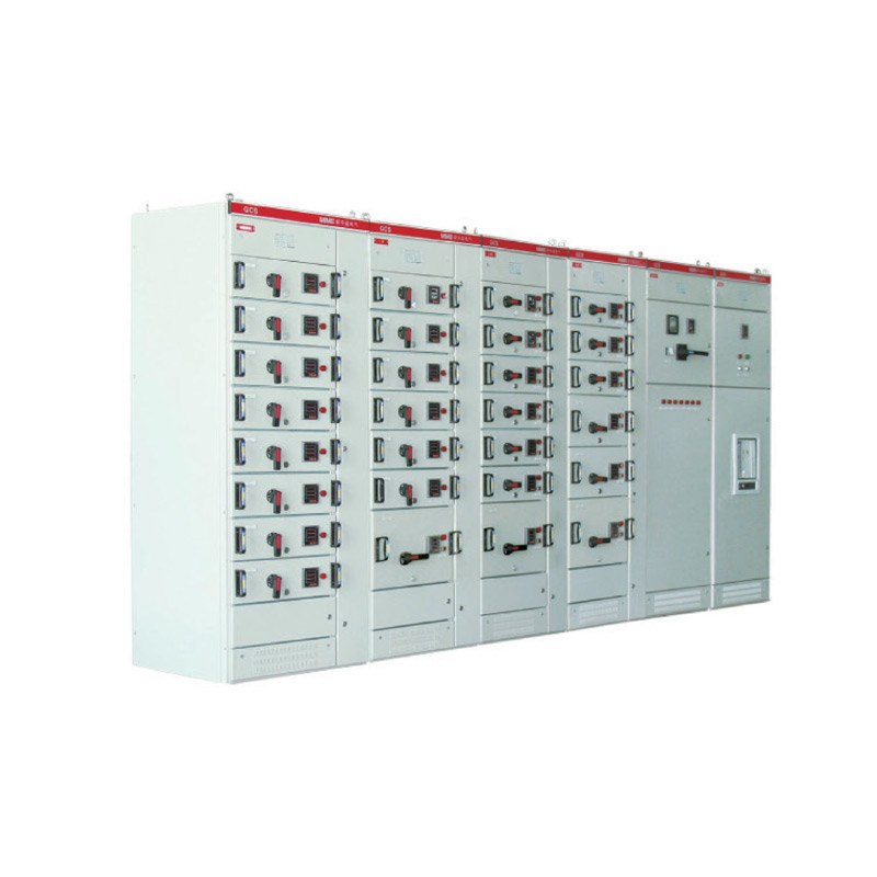
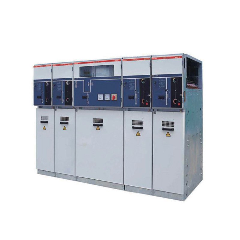
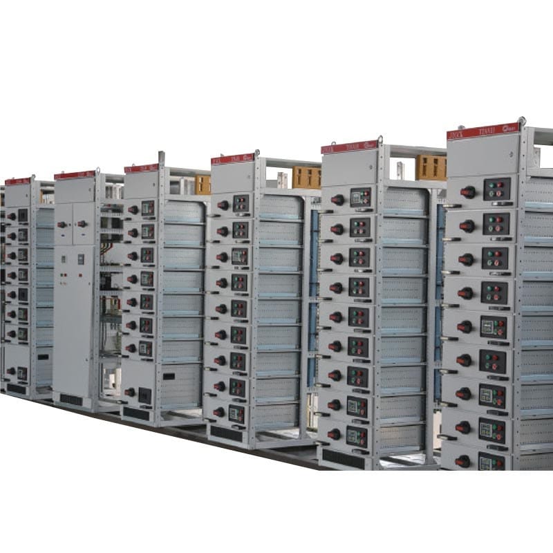
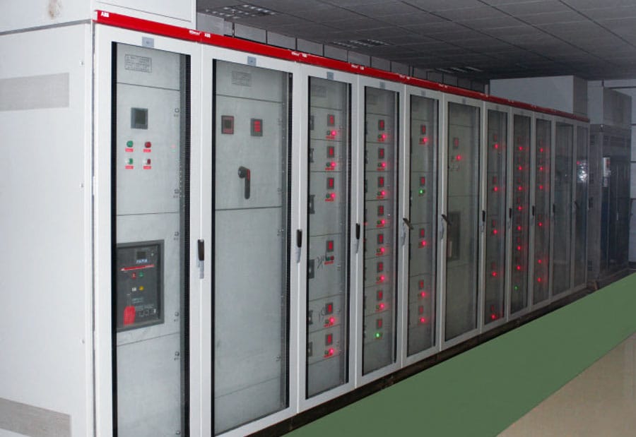
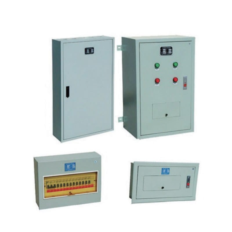
For this reason, a Medium Voltage Transformer should be treated as one part of a coordinated power distribution system rather than as an independent product. The transformer, medium-voltage switchgear, downstream distribution cabinets, cables, protection devices, and connected loads should all be evaluated around the same electrical design.
Confirm the Primary and Secondary Voltage First
The first step in transformer selection is confirming the actual primary and secondary voltage requirements. Although this sounds straightforward, voltage should not be treated as a single number copied from a specification sheet. The incoming network voltage, required secondary voltage, system frequency, insulation level, winding connection, grounding arrangement, and any expected voltage variation all influence the final transformer configuration.
Problems often arise when different parts of a distribution project are specified separately. The medium-voltage switchgear may be selected by one team, the transformer by another, and the downstream distribution equipment at a later stage. Each item may appear correct on its own, but the interfaces between them can create unexpected problems during installation or commissioning.
A better approach is to establish the complete electrical path before finalizing the transformer. The project’s medium-voltage distribution system should be reviewed as a coordinated arrangement of incoming circuits, transformer feeders, protection, cable routing, and downstream distribution. Once those relationships are clear, selecting the correct transformer voltage configuration becomes much more reliable.
Select Capacity According to the Real Load Profile
Transformer capacity is one of the most important selection factors, but it is also one of the easiest to oversimplify. Adding together the rated power of every connected device does not necessarily tell you how much load the transformer will actually experience during operation.
Some electrical equipment runs continuously, while other loads operate only at certain times. Large motors may require considerable starting current but consume much less power during normal operation. Production equipment may operate in cycles, while ventilation, lighting, control systems, pumps, heating equipment, and other loads can follow completely different schedules.
For this reason, the required capacity should be based on a realistic load profile. The design should consider continuous demand, simultaneous demand, short-duration peaks, motor starting, intermittent loads, and expected future additions. A transformer sized only from average demand may have insufficient margin during operating peaks, while one selected from the simple sum of every connected load may be unnecessarily oversized.
The important question is not simply how much equipment is connected. It is how much electrical demand the transformer is likely to experience under normal, peak, and foreseeable future operating conditions.
Do Not Treat Future Capacity as Arbitrary Spare Capacity
Future expansion should be part of Medium Voltage Transformer selection, especially when the electrical system is expected to support additional production equipment, building services, automation, charging loads, or new distribution feeders later.
However, leaving reasonable expansion capacity and choosing an unnecessarily large transformer are not the same thing. Future capacity should ideally be linked to a real development plan. If the project expects a certain group of loads to be added later, those loads can be incorporated into the capacity study rather than applying an arbitrary oversizing percentage without understanding how the system will evolve.
This distinction matters because transformer capacity affects more than the amount of load that can be connected. A change in transformer size may also alter fault-current calculations, cable requirements, downstream breaker ratings, equipment dimensions, ventilation needs, and installation layout.
Good expansion planning therefore asks what loads are expected to be added, when they are likely to be added, and whether the surrounding electrical equipment can accommodate them. The goal is to create a system with usable flexibility rather than simply installing more transformer capacity than the project is likely to need.
Understand the Type of Load the Transformer Will Supply
Two electrical systems can have the same apparent power demand but place very different stresses on a Medium Voltage Transformer. The difference comes from the characteristics of the connected loads.
A system dominated by stable resistive loads behaves differently from one containing large motors, variable-frequency drives, rectifiers, UPS systems, electronic power supplies, automation equipment, or other nonlinear loads. These devices can affect starting current, power factor, harmonic content, voltage behavior, and transformer heating.
Motor-heavy applications are a good example. The normal running load may fit comfortably within transformer capacity, but starting several motors within a short period can create temporary demand that causes noticeable voltage changes. In this situation, checking only the steady-state load would provide an incomplete picture.
Nonlinear loads require another type of evaluation. Harmonic currents generated by power-electronic equipment can increase transformer losses and internal heating even when the total load does not appear excessive. As modern electrical systems use more electronically controlled equipment, the quality and behavior of the load become increasingly important alongside the total capacity.
A better transformer specification therefore describes what the connected loads actually do. Understanding their operating behavior helps determine whether a standard transformer configuration is suitable or whether additional thermal, winding, monitoring, or system-design considerations are required.
Why Transformer Impedance Deserves More Attention
Transformer impedance is sometimes treated as a secondary technical parameter, but it has a direct influence on how the wider distribution system behaves. In particular, impedance affects the amount of short-circuit current available on the secondary side of the transformer.
This matters because the calculated fault current is used when selecting downstream circuit breakers, busbars, cables, protection settings, and other equipment that must withstand or interrupt abnormal current. If transformer impedance changes, the fault-current level may change as well.
Lower impedance generally allows a higher available short-circuit current, while higher impedance can reduce fault current but may have a greater influence on voltage regulation during changing load conditions. Neither approach is universally better. The appropriate impedance depends on how the transformer interacts with the rest of the system.
This relationship becomes particularly important when a transformer specification changes late in a project. Increasing capacity or selecting a transformer with different impedance characteristics can make earlier protection calculations outdated. When a major transformer parameter changes, engineers should therefore check whether downstream protection and equipment ratings also need to be reviewed.
Choose the Transformer Construction Around the Application
The choice between different transformer constructions should be driven by the installation environment and operating requirements rather than by a general assumption that one design is always superior.
Dry-type transformers rely on solid insulation systems and generally depend strongly on appropriate airflow for thermal management. They can be well suited to many installations where their structure matches the electrical room, environmental requirements, maintenance strategy, and overall system design. However, restricted ventilation, high ambient temperature, or significant contamination can affect their operating conditions and should be considered during selection.
Liquid-immersed transformers use insulating liquid as part of both their insulation and heat-transfer system. Their suitability depends on factors such as installation arrangement, environmental conditions, inspection access, thermal requirements, containment considerations, and how the transformer integrates with the surrounding electrical equipment.
The useful question is therefore not whether dry-type or liquid-immersed construction is better in general. The better question is which construction fits the electrical, thermal, physical, and maintenance conditions of the particular project.
Evaluate Cooling and Temperature Before Finalizing the Layout
A transformer converts a portion of electrical energy into heat during operation, and that heat must be dissipated effectively. Thermal management is therefore not just a transformer specification; it is also an installation issue.
Ambient temperature, airflow, room ventilation, enclosure arrangement, nearby heat-producing equipment, clearance, contamination, and loading pattern can all influence transformer operating temperature. A Medium Voltage Transformer that performs correctly in one installation may face very different thermal conditions in another even when the electrical load is similar.
This is why equipment-room planning should take place at the same time as transformer selection. A transformer may physically fit into the allocated space while still lacking sufficient airflow or maintenance clearance. Likewise, several pieces of electrical equipment placed in a compact room can raise the surrounding temperature and reduce the effectiveness of the original cooling assumptions.
Long-term load behavior also affects thermal performance. A relatively stable load creates a different thermal pattern from rapidly changing demand that repeatedly heats and cools the transformer. Considering these conditions before installation provides a more realistic understanding of how the equipment is likely to operate over time.
Coordinate Transformer Protection with the Whole System
Protection should not be added after the Medium Voltage Transformer has already been finalized. It should be coordinated with the transformer’s electrical characteristics from the beginning.
On the upstream side, the protective arrangement must distinguish between acceptable transformer operating events and genuine fault conditions. On the secondary side, breakers and other protective devices need to be suitable for the available fault current and coordinated with downstream circuits.
This becomes especially important in systems with several levels of distribution. A fault on one downstream circuit should, where the protection strategy allows, be isolated without unnecessarily interrupting a much larger part of the electrical system. Achieving this type of selective operation depends on understanding the transformer, protective devices, cable characteristics, busbars, and downstream equipment as one coordinated network.
Protection coordination also affects operational continuity. A transformer and its surrounding distribution equipment may all have suitable individual ratings, but poor coordination between devices can still lead to unnecessary interruptions. For this reason, transformer selection should be reviewed together with the single-line diagram and overall protection philosophy rather than treated as a separate procurement decision.
Consider Power Quality in Modern Electrical Systems
Modern electrical systems contain an increasing number of electronically controlled loads. Variable-frequency drives, automation systems, switching power supplies, charging equipment, rectifiers, and other power-conversion devices can create operating conditions that differ significantly from traditional steady loads.
One important issue is harmonic current. Harmonics can contribute to additional losses and heating within transformers and conductors, meaning that simple apparent-power calculations may not always describe the actual thermal demand placed on the equipment. The significance of these effects depends on the type, quantity, and operating characteristics of the connected nonlinear loads.
Load variation is also becoming more important. Automated facilities can change operating states rapidly as equipment starts, stops, or adjusts output according to production requirements. A Medium Voltage Transformer may therefore experience a wide range of operating conditions rather than remaining close to one stable load point.
This does not mean every modern project requires a special transformer. It means the load study should identify whether power-quality characteristics are significant enough to affect transformer design or system coordination. When those characteristics are known early, the transformer can be evaluated on the basis of actual operating conditions rather than assumptions.
Plan Cable Routing and Installation Space Before Ordering
Electrical compatibility does not guarantee that a transformer will be easy to install. Physical integration should be checked before the equipment specification is finalized.
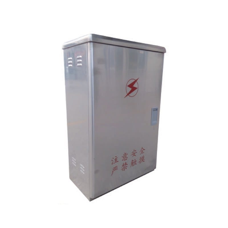
The transformer dimensions, cable entry direction, terminal position, conductor bending requirements, ventilation clearance, lifting route, inspection space, and relationship with nearby switchgear should all be reviewed against the actual installation layout.
Medium-voltage cables can require substantial termination and bending space. A drawing may show enough floor area for the transformer enclosure while leaving inadequate room to route and terminate the incoming cables correctly. Similar problems can occur on the secondary side when large conductors or bus connections must interface with downstream distribution equipment.
Maintenance access should also be included in the same review. Technicians may need space for visual inspection, testing, thermal inspection, connection checks, cleaning, and eventual equipment replacement. Designing only enough space for initial installation can create unnecessary difficulties throughout the service life of the transformer.
The strongest equipment layouts therefore consider installation, operation, maintenance, and future replacement together.
Practical Medium Voltage Transformer Selection Table
Before confirming a Medium Voltage Transformer, project teams can use the following table to make sure the most important electrical and practical factors have been reviewed.
| Selection Factor | What Should Be Confirmed | Why It Matters |
|---|---|---|
| Primary voltage | Actual incoming voltage and operating variation | Ensures compatibility with the upstream network |
| Secondary voltage | Required downstream voltage | Matches distribution equipment and connected loads |
| Transformer capacity | Normal demand, peak demand and expansion | Reduces the risk of poor capacity matching |
| Load profile | Continuous, intermittent, motor and nonlinear loads | Reveals stresses that total capacity alone may hide |
| Impedance | Transformer impedance and calculated fault level | Influences short-circuit current and protection |
| Construction | Appropriate transformer design for the installation | Connects equipment structure with site conditions |
| Cooling conditions | Ambient temperature, ventilation and airflow | Supports acceptable long-term thermal performance |
| Power quality | Harmonics, power factor and load variation | Helps identify additional electrical and thermal stress |
| Protection | Upstream and downstream protective arrangement | Supports coordinated fault isolation |
| Cable interface | Entry direction and termination space | Prevents installation conflicts |
| Maintenance access | Inspection, testing and service clearance | Makes long-term maintenance more practical |
| Future development | Realistic additional loads and system changes | Helps reduce disruptive redesign later |
The value of the table comes from considering the relationships between these factors rather than treating each row independently. Increasing transformer capacity, for example, may change fault current. Changing the transformer construction may affect ventilation requirements, and increasing expansion allowance may require a review of downstream switchgear and cable capacity.
Every major specification change should therefore be followed by one simple question: what other parts of the distribution system does this change affect?
Think About Maintenance Before the Transformer Is Installed
Maintainability is easier to design into an electrical system than to add later. A Medium Voltage Transformer may remain in service for many years, during which loads, operating practices, downstream circuits, and surrounding equipment can all change.
The installation should provide practical access for routine inspection, connection checks, cleaning, testing, and condition monitoring. Equipment labels, transformer data, drawings, protection information, and cable identification should also remain consistent with the actual installed system.
Good documentation becomes especially valuable after modifications. Without reliable records, future technicians may need to reconstruct the electrical arrangement before they can safely understand what has changed. This can make troubleshooting slower and increase the risk of incorrect assumptions.
Maintenance planning is therefore part of transformer selection. A transformer that meets today’s electrical requirements but is difficult to inspect, understand, or service may create unnecessary operational problems later.
Common Medium Voltage Transformer Selection Mistakes
One of the most common mistakes is selecting a transformer almost entirely from voltage and rated capacity. Those values are essential, but they do not describe motor starting, harmonics, fault current, operating environment, cooling, or future changes in demand.
Another mistake is assuming that a larger transformer is automatically a safer choice. Additional capacity can be valuable when future demand is clearly defined, but arbitrary oversizing may change the electrical characteristics of the distribution system without providing meaningful operational benefit.
Transformer impedance is also frequently overlooked during early equipment comparisons. If impedance is considered only after downstream switchgear and protection have already been selected, changes to the transformer specification can require parts of the distribution design to be reviewed again.
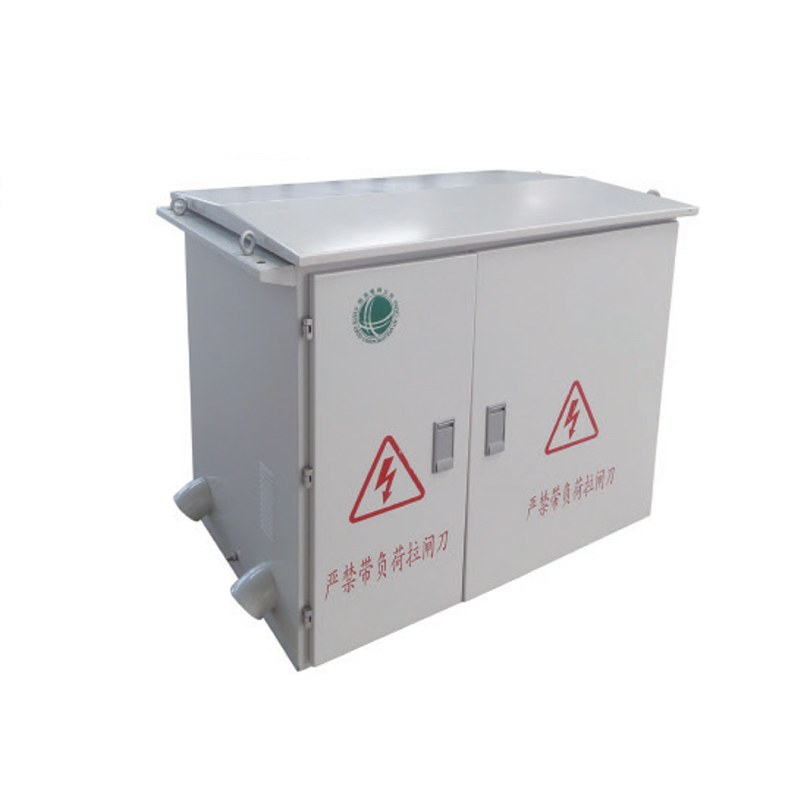
Physical installation is another common source of avoidable problems. A transformer that fits into the room may still leave insufficient space for cable termination, ventilation, inspection, lifting, or maintenance.
Finally, transformer selection can become fragmented when different pieces of equipment are purchased independently. A more reliable approach is to evaluate the transformer as part of the complete distribution path from the incoming medium-voltage supply to the downstream loads.
A Five-Step Method for Choosing the Right Transformer
A practical Medium Voltage Transformer selection process can be organized into five stages. The first stage is electrical definition. Confirm the incoming voltage, required secondary voltage, frequency, grounding arrangement, and the relationship between the transformer and surrounding equipment.
The second stage is load analysis. Build a realistic picture of continuous demand, simultaneous loading, motor starting, nonlinear loads, peak demand, and justified future expansion. This stage should explain how the system actually operates rather than simply listing connected equipment.
The third stage is system coordination. Review impedance, fault current, protective-device ratings, cable requirements, downstream busbars, and voltage behavior together. This helps ensure that changes to the transformer do not create hidden problems elsewhere in the system.
The fourth stage is physical verification. Confirm construction type, cooling requirements, installation environment, cable routing, equipment dimensions, access, and maintenance space before the specification is approved.
The fifth stage is lifecycle review. Consider how the transformer will be inspected, documented, expanded, and integrated with future system changes. A suitable transformer should make sense not only at commissioning but also after years of operation.
Following these five stages creates a stronger specification than comparing products by a small group of nameplate values alone.
Conclusion
Selecting a Medium Voltage Transformer is ultimately a system-engineering decision rather than a simple comparison of voltage and capacity. The transformer must fit the electrical network, but it must also work with the actual load profile, protection strategy, fault-current level, thermal environment, cable arrangement, installation space, and long-term operating plan.
The strongest transformer specifications begin with accurate project information. Capacity should reflect realistic demand rather than assumptions, while impedance should be reviewed together with downstream protection. Cooling and installation access should be planned before the room layout is finalized, and modern load characteristics should be considered whenever nonlinear or rapidly changing electrical equipment forms a meaningful part of the system.
The goal is not to choose the largest or most heavily specified transformer available. It is to select a Medium Voltage Transformer that operates reliably within the complete distribution system, remains practical to maintain, and provides reasonable flexibility as electrical requirements evolve.
FAQ
What is a Medium Voltage Transformer?
A Medium Voltage Transformer changes electrical voltage between medium-voltage and downstream circuits while forming an important interface within the distribution system. Its capacity, impedance, construction, cooling, and protection characteristics can affect surrounding electrical equipment and overall system performance.
How do I choose the correct Medium Voltage Transformer capacity?
Capacity should be based on actual demand rather than simply adding every connected load. Review simultaneous operation, continuous loads, motor starting, nonlinear equipment, peak conditions, and realistic future expansion to determine a capacity that matches how the system will actually operate.
Why is impedance important in a Medium Voltage Transformer?
Transformer impedance influences secondary short-circuit current and voltage behavior under load. It therefore affects breaker interrupting requirements, protection settings, busbar ratings, and system coordination, making impedance an important part of the overall distribution design.
How does the installation environment affect transformer selection?
Ambient temperature, ventilation, dust, moisture, available space, cable routing, access, and surrounding equipment can all influence transformer operation. The selected transformer should therefore match both the electrical requirements and the real physical conditions of the installation.
What information should be prepared before selecting a Medium Voltage Transformer?
Useful information includes primary and secondary voltage, frequency, expected load, load characteristics, installation conditions, cooling requirements, cable arrangement, protection requirements, expected future expansion, and relevant project drawings or electrical system information.
Need Help Choosing the Right Medium Voltage Transformer?
If you’re unsure which Medium Voltage Transformer best matches your voltage level, load profile, installation environment, protection requirements, or future expansion needs, our technical team is here to help. Contact our power distribution team to discuss your project requirements and develop a configuration that fits the way your electrical system actually needs to operate.