İçindekiler Tablosu
Giriş
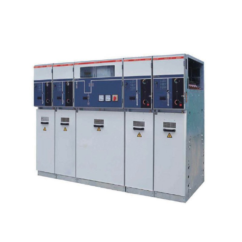
A ring main unit for renewable energy project applications has to do more than provide compact medium-voltage switching. Renewable generation sites often contain multiple electrical nodes, long cable routes, transformers, collection circuits, auxiliary loads, and distribution points that need to operate as one coordinated network. The ring main unit becomes an important interface between these elements because it can organize incoming and outgoing feeders, isolate selected sections, protect transformer circuits, and support practical network reconfiguration.
The challenge is that renewable generation does not always behave like a traditional constant-load electrical system. Generation can vary with operating conditions, sites may contain multiple separated power blocks, and future capacity expansion may introduce additional transformers or feeder routes. As a result, selecting an RMU only from voltage and rated current can leave important questions unanswered.
A suitable ring main unit for renewable energy project use should be evaluated according to network topology, system voltage, feeder arrangement, short-circuit conditions, transformer interfaces, cable connections, protection philosophy, environmental exposure, monitoring, maintenance, and future development. The following eight design factors provide a practical framework for making that selection.
Why Ring Main Units Fit Distributed Energy Networks
Many renewable energy facilities are physically distributed rather than concentrated around one electrical room. Generation equipment may be arranged across a large site, with individual blocks connected through transformers and medium-voltage cable routes before power reaches a central collection or distribution point.
This creates a natural need for repeated medium-voltage switching nodes.
A ring main unit can provide a compact point where cables arrive, continue to another section, branch toward a transformer, or are isolated for maintenance. Instead of using a large multi-panel switchgear lineup at every distributed node, an RMU can concentrate the functions required at that particular position in the network.
The concept works especially well when the electrical system is designed around clearly defined feeder sections. Each RMU can become part of a larger chain of cable routes and transformer nodes, allowing the complete system to remain organized even when the physical equipment is spread across a large project area.
This is one reason RMUs are relevant to modern renewable energy systems: the equipment can support distributed medium-voltage collection and switching without requiring every network node to perform the same functions as a central switchgear station.
1. Define the Network Topology Before Selecting the RMU
The first step is understanding how power is expected to move through the project.
A renewable energy site may use a radial arrangement, a ring arrangement, or a structure that combines elements of both. The choice affects how many incoming and outgoing circuits the ring main unit needs and how those circuits should be operated during normal conditions and maintenance.
In a radial network, power normally follows one defined path. The RMU may mainly provide feeder switching, transformer connection, and local isolation.
A ring network introduces another level of flexibility because different distribution sections can be interconnected. Depending on the operating strategy, one network section can potentially be isolated while another route continues to support the remaining system.
The important point is that the RMU configuration should follow the topology rather than determine it.
Project teams should first map the generating blocks, transformers, cable routes, collection points, and central distribution equipment. Each proposed RMU can then be assigned a specific role within that network.
Without this step, it is easy to specify the same RMU arrangement repeatedly even when different nodes perform different electrical functions.
2. Confirm the System Voltage and Insulation Requirements
Voltage level establishes one of the fundamental requirements of a ring main unit for renewable energy project use.
The RMU, cables, transformer interfaces, switching devices, and insulation system all need to correspond to the same electrical network. Voltage should therefore be confirmed at the system level before the equipment configuration is finalized.
The site may include several voltage levels.
Generation equipment can operate at a lower voltage before transformers increase the voltage for collection and distribution. The RMU generally sits within the medium-voltage section of this architecture, so its insulation and switching requirements are determined by that part of the network rather than by the voltage produced directly by the generating equipment.
Insulation coordination also needs to be considered together with connected equipment.
Cable terminations, transformer connections, internal switching components, and other interfaces should all be suitable for the network conditions. A correct RMU voltage rating does not compensate for an incompatible cable accessory or transformer interface.
This is why the voltage level should be treated as a system specification rather than a cabinet label.
3. Match the Feeder Configuration to the Actual Site Layout
One of the main advantages of an RMU is its ability to combine several feeder functions in a compact arrangement.
However, the number of feeders should come from the project layout rather than from a standard configuration.
A typical network node may require an incoming cable, an outgoing cable continuing toward another section, and a transformer feeder. Another node may need two outgoing routes or a different transformer arrangement.
The correct configuration depends on what happens electrically at that exact location.
Engineers should identify whether each circuit is:
an incoming feeder,
a continuing network feeder,
a transformer feeder,
a branch toward another distribution node,
or a reserved future connection.
This feeder map also helps determine which circuits need switching and which require protection.
The RMU should make the network easier to understand. If several unrelated feeders are placed into one compact unit simply because physical space is available, future operation can become unnecessarily complicated.
For projects where the feeder architecture is already defined, the site’s Ring Main Unit product category can be used as the product-level entry point for matching an RMU to the actual medium-voltage distribution requirement.
4. Evaluate Short-Circuit Conditions at Every RMU Node
Normal operating current describes only one part of the electrical requirement.
A ring main unit also needs to withstand the electrical and mechanical stress associated with credible fault conditions at its installation point.
Available short-circuit current can vary across a renewable energy collection network. Transformer characteristics, cable length, conductor impedance, network topology, and the number of connected sources can influence the fault level at different nodes.
This means one fault-current assumption should not automatically be applied to every RMU in a large project.
A node located close to a central collection point may experience different electrical conditions from one located farther along a cable route.
Network reconfiguration can also change fault conditions. If switching allows different feeder sections to become interconnected, the project should consider the possible operating configurations rather than evaluating only the most common normal arrangement.
The RMU’s switching and protection components therefore need to be coordinated with the actual fault study.
This is particularly important when future expansion is planned, because additional generation blocks or transformer capacity can change the electrical characteristics of the network.
5. Coordinate Transformer Protection with the RMU
Transformers are often closely connected to RMUs in distributed renewable energy networks.
The RMU may contain a dedicated transformer feeder that uses a circuit breaker, fuse-based protection, or another configuration depending on the project design.
The appropriate arrangement depends on transformer capacity, fault conditions, protection philosophy, operating requirements, and the coordination expected between upstream and downstream protective devices.
Transformer protection should not be selected only by matching the transformer rating to a standard feeder configuration.
The project team should consider what happens during a transformer-side fault, what device is expected to operate, how quickly the affected section should be isolated, and whether other parts of the network should remain energized.
Protection coordination also needs to account for normal transformer behavior.
Energization can create operating conditions that differ from steady-state current, so protective devices need to distinguish expected transformer behavior from conditions that require fault isolation.
The goal is a protection strategy in which the transformer feeder, RMU, upstream switching equipment, and downstream distribution system operate as one coordinated hierarchy.
6. Give Cable Terminations Enough Space and Attention
Cable interfaces are one of the most important physical design issues for a ring main unit for renewable energy project installations.
Distributed energy projects can contain long medium-voltage cable routes connecting multiple electrical nodes. Every time those routes enter an RMU, the cable has to be bent, supported, prepared, terminated, identified, and eventually inspected.
These physical requirements should influence RMU layout from the beginning.
Cable size, conductor material, overall diameter, entry direction, termination type, and minimum bending requirements all affect the space required at the equipment.
A compact RMU may save footprint while still needing substantial working space below or around the cable compartment.
Civil works therefore need to be coordinated with equipment design.
Cable trenches, foundations, openings, and termination positions should align before installation begins. If the cable route and RMU arrangement are designed separately, installers may face difficult bends or restricted access once the equipment arrives on site.
Cable identification is equally important. Where multiple RMUs form one collection network, every incoming and outgoing route should remain clearly traceable through drawings and physical labels.
7. Consider Outdoor Conditions and Environmental Exposure
Renewable energy sites can place medium-voltage equipment in demanding environments.
Temperature variation, dust, moisture, condensation, airborne contamination, solar heating, wind-driven particles, and local site conditions can all influence equipment performance.
An outdoor ring main unit should therefore be selected according to the actual environment rather than simply being described as weather resistant.
Enclosure protection is only one part of the issue.
Cable-entry sealing, internal condensation control, ventilation or thermal behavior where applicable, corrosion protection, foundation design, and maintenance access all contribute to long-term reliability.
Condensation deserves particular attention because it can occur even when external rainwater does not directly enter the enclosure. Temperature changes can create internal moisture on surfaces, particularly where equipment experiences large differences between daytime and nighttime conditions.
Environmental planning should also consider maintenance.
An RMU may technically fit within a narrow installation area, but technicians still require reasonable access for operation, inspection, cable work, and fault investigation.
The best installation therefore balances compact equipment with adequate surrounding working space.
8. Plan Monitoring and Remote Operation Around Real Needs
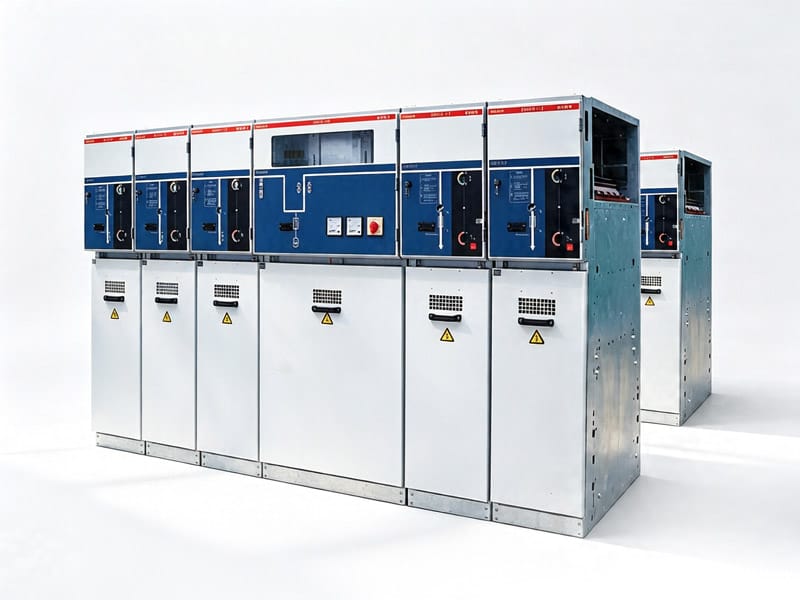
Renewable energy networks can contain many distributed electrical nodes, making monitoring increasingly useful.
An RMU may provide information about switch position, feeder status, fault indication, current, voltage, alarms, or other electrical conditions depending on the configuration and wider control system.
The value of this information increases when operators can use it to answer clear questions.
Which section is energized?
Which feeder has experienced a fault?
Has one part of the network been isolated?
Is a switching device in the expected position?
Is one feeder carrying substantially more current than expected?
These questions become especially important when RMUs are spread across a large site.
Remote status information can reduce the time required to determine what has happened after an abnormal event, but remote control should be designed with clear operating logic and interlocking.
The purpose of digital functionality is not to make every RMU as complex as possible. It is to provide the level of visibility and control that improves operation of the actual network.
Ring Main Unit for Renewable Energy Project Checklist
The following table summarizes the main information that should be reviewed before finalizing the RMU configuration.
| Design Factor | What to Confirm | Neden Önemli |
|---|---|---|
| Network topology | Radial, ring, or combined structure | Defines feeder arrangement and switching logic |
| System voltage | Actual medium-voltage network level | Establishes insulation and equipment compatibility |
| Feeder quantity | Incoming, outgoing, transformer and future circuits | Determines RMU configuration |
| Nominal akım | Expected feeder operating current | Supports normal electrical operation |
| Fault conditions | Short-circuit level at each node | Influences switching and withstand requirements |
| Transformer interface | Capacity and protection strategy | Defines transformer feeder arrangement |
| Cable connection | Size, entry direction and termination method | Determines physical installation requirements |
| Environment | Temperature, moisture, dust and contamination | Influences enclosure and site design |
| Monitoring | Status, alarms, fault indication and remote functions | Supports distributed network operation |
| Maintenance | Access, isolation and inspection requirements | Improves lifecycle serviceability |
| Expansion | Planned additional generation blocks or feeders | Reduces future network reconstruction |
These factors should be reviewed together. Adding another transformer can change feeder quantity, cable routing, load current, fault conditions, and protection requirements at the same time.
How RMUs Support Sectionalized Medium-Voltage Networks
One practical value of an RMU is the ability to divide a medium-voltage network into identifiable sections.
Instead of treating a long cable collection route as one uninterrupted electrical path, switching points can be placed at strategic nodes. These points provide locations where parts of the network can be isolated according to the system design.
This can be useful during planned maintenance.
If a particular cable section or transformer needs to be removed from service, the switching strategy can be developed so that the affected section is clearly separated before work begins.
Sectionalization can also support fault investigation.
When an abnormal condition occurs, identifying the affected network section can be easier when the distribution architecture already contains clearly defined switching nodes.
However, the value depends on proper planning.
Adding more switching points than the network actually needs can increase equipment complexity. The objective is therefore not to maximize the number of RMUs but to position them where they provide a meaningful electrical function.
Ring Network or Radial Network: Which Is More Suitable?
Both structures can be used depending on the project.
A radial system is usually simpler to understand because each downstream point is supplied through one primary path. Protection and operating logic can therefore be relatively straightforward.
A ring arrangement can provide more routing flexibility because network sections are interconnected.
However, that flexibility needs to be supported by clear operating procedures, switching logic, protection coordination, and accurate feeder identification.
The right structure depends on the importance of continuity, physical cable routes, project size, fault-management strategy, and the way the site is expected to expand.
A ring main unit can support either architecture, so its name should not lead designers to assume that every RMU installation must operate as a permanently closed ring.
The network topology should remain an engineering decision based on the complete project.
How Variable Generation Affects RMU Selection
Renewable generation can change over time because the primary energy source and operating conditions vary.
The RMU does not control the generation process itself, but changing power flow can influence the electrical conditions seen by the collection system.
This makes load-flow analysis important.
Engineers should understand expected minimum, typical, and maximum operating conditions rather than designing around one fixed generation level.
Power-flow direction can also deserve attention in certain network architectures. The protection and monitoring strategy should reflect the way current may move through the system under different operating states.
Equipment should therefore be selected around the complete range of credible conditions.
This does not necessarily mean choosing larger equipment. It means ensuring that current ratings, protection, measurement, and control assumptions remain valid throughout the expected operating envelope.
How Future Generation Expansion Changes the Design
Renewable projects are sometimes developed in stages.
An initial installation may include several generation blocks, while additional sections are expected later. This creates a strong reason to plan RMU locations and feeder routes carefully from the beginning.
Future expansion can affect more than feeder quantity.
Additional capacity may change current flow through existing circuits, available short-circuit current, transformer requirements, cable loading, protection coordination, and the role of existing RMUs.
A spare RMU panel or connection position therefore does not automatically mean the electrical system is ready for expansion.
The project should determine whether the upstream network, cables, transformers, protection, and central distribution equipment can support the additional capacity.
Where expansion is genuinely planned, physical provision and electrical capacity should be developed together.
This creates a more useful future-ready design than simply installing unused switching positions.
RMU Maintenance in Distributed Energy Sites
Maintenance planning becomes especially important when multiple RMUs are installed across a large project site.
A central switchgear room concentrates equipment in one location, but distributed RMUs may require maintenance teams to travel between several electrical nodes.
Standardized configuration can therefore provide practical benefits.
When switching arrangements, labels, operating procedures, and documentation follow a consistent logic, technicians can understand each node more quickly.
Inspections should consider enclosure condition, switch operation, cable terminations, grounding, indicators, protection components, signs of moisture or contamination, and the surrounding installation environment.
Maintenance records should also identify each RMU clearly.
If multiple units use similar configurations, records need unique equipment identifiers so that abnormal conditions can be traced to the correct network location.
A distributed system remains manageable when its documentation is as organized as its electrical architecture.
Common RMU Selection Mistakes in Renewable Energy Projects
One common mistake is selecting the same RMU configuration for every network node.
Standardization has advantages, but different locations can have different feeder functions, fault levels, cable arrangements, or transformer requirements. The equipment should remain standardized where practical without ignoring genuine electrical differences.
Another mistake is focusing on compact dimensions before cable termination requirements are known. Medium-voltage cables can require significant working and bending space even when the RMU itself is relatively small.
Future expansion can also be misunderstood. Installing a spare feeder position does not create additional network capacity unless the rest of the system is designed to support it.
Environmental conditions are another area that deserves more attention. A suitable outdoor enclosure still needs correct installation, sealing, foundation design, condensation management, and maintenance access.
Finally, monitoring should not be added without a clear operating purpose. Every signal or remote-control function should support a defined maintenance, fault-management, or network-control requirement.
Information to Prepare Before Selecting the RMU
A strong equipment specification begins with project information.
The single-line diagram should show the generating blocks, transformers, RMU nodes, cable routes, central distribution equipment, and expected switching arrangement.
The project team should also prepare system voltage, feeder current, transformer capacity, short-circuit information, cable specifications, installation environment, network topology, and protection philosophy.
For each RMU node, define which circuits are incoming, outgoing, transformer-connected, or reserved for future use.
Monitoring requirements should be described separately rather than assumed.
If remote operation is needed, the project should define which switching functions require remote control and how status and alarms will be integrated into the wider system.
Providing this information before product configuration greatly reduces the risk of modifying equipment after the cable network and civil layout have already been established.
A Four-Stage RMU Selection Method
A practical ring main unit for renewable energy project selection process can be divided into four stages.
The first stage is network planning. Define the topology, voltage level, transformer positions, cable routes, switching nodes, and expected power-flow conditions.
The second stage is electrical configuration. Establish rated current, feeder quantity, short-circuit requirements, transformer protection, switching functions, and protection coordination.
The third stage is physical integration. Review cable entry, termination space, enclosure requirements, foundation, environmental exposure, operating clearance, and maintenance access.
The fourth stage is lifecycle planning. Confirm monitoring, documentation, future expansion, inspection strategy, spare feeder requirements, and how changes to the generation network will be managed.
Using these four stages helps ensure that the RMU configuration follows the renewable energy network rather than forcing the network to fit a standard cabinet arrangement.
Sonuç
A ring main unit for renewable energy project applications should be selected around the structure of the complete medium-voltage network. The RMU is not simply a compact switching cabinet; it can become a critical node connecting cable feeders, transformers, protection, isolation, monitoring, and future distribution expansion.
The selection process should begin with network topology and system voltage, followed by feeder configuration, current and fault conditions, transformer protection, cable terminations, environmental requirements, and monitoring strategy.
Renewable energy sites can also introduce additional considerations because generation blocks may be distributed across large areas and project capacity can develop in stages. This makes feeder identification, sectionalization, standardized maintenance, and realistic expansion planning particularly important.
The strongest design does not place an RMU at every possible point or maximize the number of available functions. It places the correct switching and protection functions at the nodes where they support the actual network.
When the RMU is coordinated with cables, transformers, protection, site layout, and future development, it can provide a compact and maintainable foundation for medium-voltage distribution throughout a renewable energy project.
SSS
What does a ring main unit do in a renewable energy project?
A ring main unit can connect and switch medium-voltage cable feeders, provide transformer-feeder protection, isolate selected network sections, and support organized distribution between separated generation blocks, transformers, and central electrical collection points.
How do I select a ring main unit for renewable energy project use?
Start with network topology, system voltage, feeder quantity, rated current, short-circuit conditions, transformer capacity, protection strategy, cable termination requirements, environmental conditions, monitoring needs, and realistic future expansion.
Can an RMU be used in a radial renewable energy network?
Yes. An RMU can support radial as well as ring-based distribution arrangements. The configuration should follow the actual feeder structure and switching requirements rather than assuming that every ring main unit must operate within a permanently closed ring network.
Why is cable planning important when selecting an RMU?
Medium-voltage cables require suitable entry, bending, support, termination, identification, and maintenance space. A compact RMU can still require substantial cable working space, so equipment, trenches, foundations, and cable routes should be coordinated before installation.
Should future expansion be included in the RMU design?
Yes, when expansion is realistically planned. Future feeders may affect current, fault level, protection, cable routing, transformers, and central distribution equipment. Spare physical positions are useful only when the wider electrical network can support the additional capacity.
Need Help Choosing the Right Ring Main Unit?
If your project requires a ring main unit for distributed medium-voltage switching, transformer connection, cable routing, or future feeder expansion, contact our technical team with your single-line diagram, system voltage, transformer information, feeder arrangement, and installation conditions for configuration support.