Table of Contents
Introduction
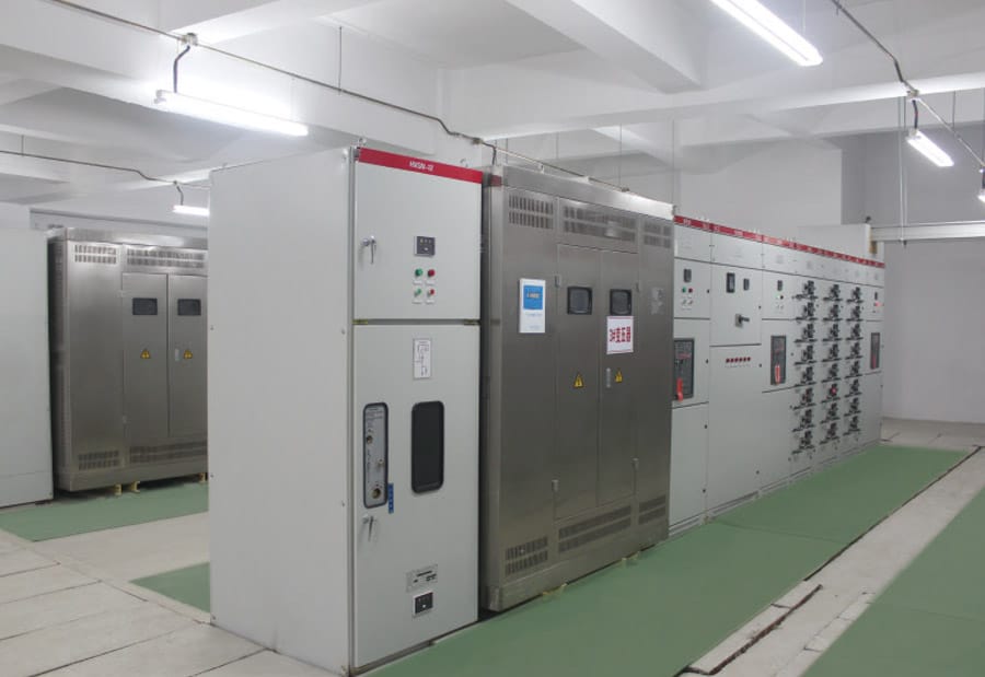
Electricity must be divided, controlled, and protected before it can safely reach lighting systems, machinery, sockets, control equipment, and other electrical loads. An Electrical Distribution Box performs this task by receiving power from an upstream source and separating it into multiple outgoing circuits.
Each outgoing circuit is connected to a specific group of loads and protected by an appropriate device. If one branch experiences an overload, short circuit, or leakage fault, the affected circuit can be disconnected without necessarily interrupting every other part of the electrical system.
This organized approach makes power distribution safer, easier to maintain, and more adaptable. However, reliable performance depends on much more than placing several circuit breakers inside an enclosure. Busbar capacity, conductor size, grounding continuity, heat dissipation, internal spacing, cable entry, protective-device coordination, and labeling all influence how well the system works.
This guide explains the operating principle of an Electrical Distribution Box, the function of its main components, the path electricity follows through the enclosure, and the factors that affect long-term reliability.
What Is an Electrical Distribution Box?
An Electrical Distribution Box is an electrical assembly that receives an incoming power supply and divides it into separate downstream circuits. Each outgoing branch usually supplies a defined load, such as lighting, equipment, sockets, motors, control systems, or auxiliary devices.
The general term distribution board describes equipment that divides an incoming electrical supply into subsidiary circuits. Protective devices such as circuit breakers or fuses are normally assigned to these individual circuits.
An Electrical Distribution Box performs three closely connected functions:
- Power distribution
- Circuit protection
- Electrical isolation
Power distribution ensures that electricity reaches the correct loads. Circuit protection limits damage caused by abnormal current conditions. Isolation allows individual branches or the complete downstream system to be disconnected for inspection, repair, or equipment replacement.
A Controlled Distribution Point
Without a structured distribution point, multiple loads would have to share poorly organized connections. This would make fault identification, circuit protection, expansion, and maintenance considerably more difficult.
The box creates a defined electrical route. Incoming conductors enter through the main section, power is transferred to internal busbars, and individual circuit breakers direct electricity to separate outgoing circuits.
More Than an Enclosure
The enclosure prevents accidental contact with live components and protects internal devices from environmental exposure. However, the enclosure alone does not determine product quality.
A reliable system also requires a logical internal layout, secure terminals, correctly rated components, suitable cable spacing, clear circuit identification, and enough room for inspection and future modification.
What Are the Main Components of an Electrical Distribution Box?
The design of an Electrical Distribution Box varies according to voltage, phase configuration, circuit quantity, protection requirements, and installation environment. Most systems nevertheless contain several common components.
Main Incoming Switch
The main switch controls the electrical connection between the incoming supply and the downstream distribution section. When closed, it allows power to reach the internal busbars. When opened, it disconnects the downstream circuits.
The incoming side of the main switch may remain energized even when the switch is open. For this reason, operating the main switch should not automatically be treated as confirmation that every internal part is safe to touch.
Main Protective Device
Some designs use a main protective device to protect the complete distribution assembly from excessive current. The main protection may be integrated with the incoming switch or installed as a separate component.
Its current rating and interruption capability must match the system design. A device may have an appropriate rated current but still be unsuitable if it cannot safely interrupt the available fault current.
Busbars
Busbars are conductive metal bars that transfer power from the incoming section to multiple outgoing protective devices. They provide a compact and organized distribution path inside the enclosure.
Busbar performance depends on several factors:
- Rated current
- Conductive material
- Cross-sectional area
- Insulation
- Mechanical support
- Connection quality
- Internal temperature
An undersized busbar or loose busbar connection can create excessive heat, voltage drop, insulation damage, and reduced system reliability.
Circuit Breakers
Circuit breakers control and protect individual outgoing circuits. Under normal conditions, they allow current to flow to connected loads. When abnormal current is detected, they open the circuit.
Different circuits may require different breaker ratings or protective characteristics. A lighting circuit, motor circuit, heating circuit, and control circuit may behave differently during startup and normal operation.
Neutral Bar
The neutral bar provides a common termination point for neutral conductors. In circuits requiring a neutral connection, current returns from the load through the neutral conductor and into the neutral bar.
Neutral conductors can carry substantial current during normal operation. They must therefore be properly sized, securely terminated, and clearly identified.
Grounding Bar
The grounding bar connects protective grounding conductors from outgoing circuits to the grounding system. It should not normally carry continuous operating current.
If an energized conductor contacts exposed conductive material, the grounding path allows fault current to flow. This helps the relevant protective device disconnect the affected circuit quickly.
DIN Rails and Mounting Plates
DIN rails are commonly used to secure modular circuit breakers, relays, contactors, and other control devices. Mounting plates may be used for larger components or customized assemblies.
A stable mounting structure prevents movement, maintains electrical clearances, and allows components to be arranged in a serviceable layout.
Cable Entry and Sealing Components
Cable glands, entry plates, grommets, and sealing components guide conductors into the enclosure. They also reduce mechanical strain and help maintain environmental protection.
Poorly managed entries can allow dust, moisture, or debris into the box. They may also place excessive force on terminals when cables move or bend.
How Does an Electrical Distribution Box Work Step by Step?
The operation of an Electrical Distribution Box can be understood by following the path electricity takes from the incoming supply to the connected load.
Step 1: Power Enters the Enclosure
Incoming electrical conductors enter the box through designated cable openings. Depending on the system, these conductors may include one or more phase conductors, a neutral conductor, and a protective grounding conductor.
Cables should be mechanically supported so their weight does not pull directly on electrical terminals. Appropriate bending space is also needed to prevent insulation damage or excessive conductor stress.
Step 2: Power Reaches the Main Switch
The incoming phase conductors connect to the main switching device. When the main switch is closed, electricity can move into the internal distribution section.
The main switch provides a single control point for the downstream system. It is especially important during maintenance, emergency shutdown, system testing, and equipment replacement.
Step 3: The Busbars Become Energized
After passing through the main device, electricity reaches the busbars. The busbars distribute power across the row of outgoing circuit breakers.
In a single-phase arrangement, one phase busbar may supply the outgoing breakers. In a three-phase arrangement, separate busbars carry the three phases.
Step 4: Circuit Breakers Supply Individual Branches
Each circuit breaker connects a section of the busbar to an outgoing conductor. When the breaker is closed, power flows through the device and into the branch circuit.
This arrangement allows each circuit to be protected and controlled independently. One breaker may supply lighting, while another supplies equipment, sockets, pumps, controls, or ventilation systems.
Step 5: Electricity Reaches the Load
The outgoing conductor carries electrical energy from the breaker to the connected load. The load converts that energy into light, heat, movement, control signals, or another useful output.
The conductor size must be appropriate for the expected current, installation method, ambient conditions, route length, and protective-device rating.
Step 6: Current Returns Through the Neutral
For circuits using a neutral conductor, current returns from the load to the neutral bar. It then continues through the upstream neutral connection.
The neutral forms part of the normal current path. A loose or undersized neutral connection may cause overheating, voltage instability, irregular equipment performance, or conductor damage.
Step 7: Grounding Supports Fault Protection
Protective grounding conductors remain connected to exposed conductive parts throughout the system. They do not normally carry operating current.
If insulation fails and an energized conductor contacts a metal enclosure or equipment frame, the grounding path carries fault current. The increased current should cause the protective device to open the circuit.
How Does an Electrical Distribution Box Protect Electrical Circuits?
An Electrical Distribution Box contains devices designed to recognize abnormal conditions and interrupt electricity before conductors or equipment are seriously damaged.
Overload Protection
An overload occurs when a circuit carries more current than its intended continuous capacity. It may result from excessive connected equipment, mechanical problems in a motor, unsuitable circuit design, or changes in how the system is used.
Overload protection does not always operate immediately. Many electrical loads briefly draw higher current during startup, so protective devices must distinguish between acceptable temporary demand and dangerous sustained overload.
Short-Circuit Protection
A short circuit occurs when conductors at different electrical potentials come into unintended contact through a low-resistance path. This can produce a rapid and extremely high current.
Short-circuit protection must respond quickly. The protective device must also be capable of interrupting the expected fault current without causing uncontrolled damage inside the enclosure.
Leakage and Ground-Fault Protection
Leakage current occurs when electricity leaves its intended conductive path. It may flow through damaged insulation, contaminated surfaces, exposed metal, moisture, or another unintended route.
Leakage-sensitive devices compare the outgoing and returning current. When the difference exceeds a defined threshold, the circuit is disconnected.
This function is different from standard overcurrent protection. A dangerous leakage fault may occur without drawing enough current to trip a conventional circuit breaker.
Surge Protection
Voltage surges may be produced by switching operations, electrical disturbances, or other transient events. Surge protective devices limit these temporary voltage increases by diverting excess energy away from sensitive equipment.
Surge protection should be selected according to the electrical system, exposure conditions, connected equipment, and overall protection strategy.
Circuit Isolation
Individual circuit breakers allow specific branches to be isolated. This reduces the area affected by maintenance or a fault.
For example, a lighting circuit can be disconnected while machinery circuits remain operational. Effective isolation depends on accurate labeling and confirmation that no alternative supply path is present.
What Is the Difference Between Neutral and Ground?
Neutral and grounding conductors perform different functions, even though they may be associated with similar reference potentials within parts of an electrical system.
Neutral Carries Operating Current
The neutral conductor completes the normal current path for many loads. Current flows through it whenever the connected circuit is operating.
Neutral terminals may overheat if they are loose, undersized, damaged, or exposed to currents that were not considered during the original design.
Ground Carries Fault Current
The grounding conductor is primarily a safety path. It connects exposed metal parts to the grounding system so that fault current can operate protective devices.
Under normal conditions, the grounding conductor should not be used as a substitute for the neutral conductor.
Improper Connections Create Hidden Risks
Neutral and ground may be connected at a designated point in the overall electrical system, but they should not be joined randomly inside every distribution box.
An incorrect connection can place normal return current on metal enclosures, grounding conductors, cable trays, or equipment frames. This may create shock hazards and interfere with protective-device operation.
Single-Phase and Three-Phase Electrical Distribution Boxes
Both arrangements receive, divide, and protect electrical power. Their internal configuration and load-management requirements are different.
Single-Phase Electrical Distribution Box
A single-phase box is often used for lighting, sockets, controls, and moderate electrical loads. One phase conductor supplies outgoing breakers, while neutral conductors return through the neutral bar.
The box should be selected according to total demand, number of circuits, protective requirements, installation environment, and available expansion space.
Three-Phase Electrical Distribution Box
A three-phase box contains three separate phase paths. It may supply three-phase equipment directly or distribute individual single-phase circuits across the available phases.
Three-phase distribution is useful when the system includes motors, production equipment, pumps, compressors, larger electrical loads, or many branch circuits.
Why Load Balancing Matters
Single-phase loads connected to a three-phase system should be distributed across the phases as evenly as practical.
Poor load balance may cause:
- One phase to carry excessive current
- Uneven busbar and conductor heating
- Higher neutral current
- Voltage variation
- Unnecessary protective-device operation
- Reduced usable system capacity
Load balancing should be reviewed after installation because operating patterns can change as equipment is added, removed, or used at different times.
Electrical Distribution Box Components and Their Functions
| Component | Main function | Normal operating condition | Common concern |
|---|---|---|---|
| Main switch | Controls the incoming supply | Carries the total downstream load | Incorrect rating or unclear isolation |
| Main protective device | Protects the complete assembly | Responds to excessive current | Inadequate interruption capability |
| Busbar | Distributes power internally | Supplies multiple breakers | Loose joints or excessive temperature |
| Circuit breaker | Protects an outgoing branch | Carries normal branch current | Incorrect coordination with the cable |
| Neutral bar | Connects neutral conductors | Carries return current | Loose or insufficient terminals |
| Grounding bar | Connects protective conductors | Carries current during faults | Poor continuity or corrosion |
| Enclosure | Prevents contact and exposure | Protects internal equipment | Inadequate sealing or ventilation |
| Cable gland | Supports and seals cables | Maintains cable position | Poor fit or mechanical strain |
| DIN rail | Supports modular components | Holds devices securely | Crowding or weak mounting |
| Circuit label | Identifies connected loads | Supports operation and maintenance | Missing or outdated information |
These components cannot be evaluated independently. A correctly rated breaker cannot compensate for an undersized conductor, damaged cable gland, loose neutral terminal, weak grounding path, or unsuitable enclosure.
How Does the Enclosure Affect Electrical Performance?
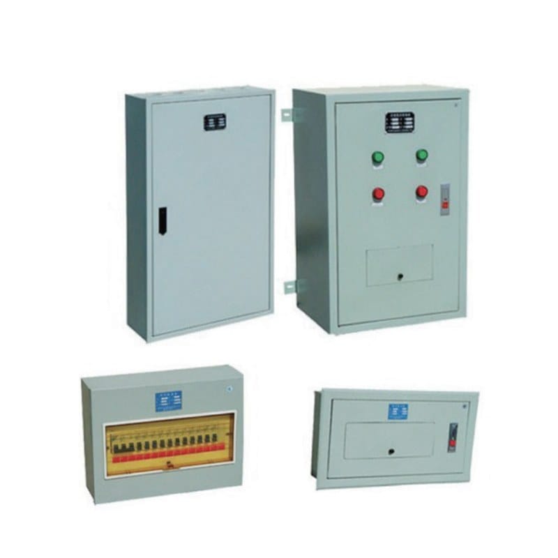
The enclosure influences safety, environmental resistance, temperature, installation quality, and maintenance access.
Protection Against Dust and Moisture
The enclosure must suit the installation environment. Conditions such as dust, humidity, water exposure, corrosion, cleaning processes, and airborne particles can affect internal components.
Door seals, cable glands, ventilation openings, fasteners, and unused cable entries all influence environmental protection. Even a suitable enclosure can lose its protective performance when openings are left unsealed.
Heat Management
Circuit breakers, busbars, terminals, transformers, relays, and conductors generate heat. Internal temperature rises when many components are installed in a confined space.
Excessive temperature can affect:
- Breaker operating characteristics
- Insulation service life
- Terminal reliability
- Electronic control devices
- Cable capacity
- Enclosure seals
A compact design is not always the most reliable design. Additional internal space can improve airflow, cable routing, maintenance access, and temperature distribution.
Mechanical Protection
The enclosure must protect components against accidental impact, vibration, and unauthorized access. Mounting arrangements should remain stable during normal operation and maintenance.
Vibration can gradually loosen electrical connections. Applications exposed to continuous movement may require additional mechanical support and more frequent inspection.
Maintenance Accessibility
Technicians need enough room to identify conductors, inspect terminals, take measurements, and replace devices. Crowded wiring can hide damaged insulation and make correct tightening difficult.
The enclosure should provide safe access while maintaining barriers around energized parts.
Common Electrical Distribution Box Problems
Many distribution faults develop gradually. They may begin as minor installation or maintenance issues before becoming serious failures.
Repeated Breaker Tripping
A breaker that repeatedly trips may indicate:
- Excessive connected load
- Short circuit
- Ground fault
- Equipment failure
- Damaged conductor
- Loose terminal
- Incorrect breaker selection
- High internal temperature
Replacing the breaker with a higher-rated device without checking the conductor and load may remove essential circuit protection.
Loose Electrical Connections
Loose connections increase electrical resistance. Increased resistance produces localized heat, which may damage insulation and further weaken the connection.
Possible warning signs include discoloration, unusual odor, unstable equipment operation, damaged insulation, intermittent power, and abnormal surface temperature.
Unbalanced Three-Phase Loads
Unbalanced loading places greater demand on one or two phases. The problem may not be visible from the circuit schedule because actual usage can differ from the original design assumptions.
Current measurements under representative operating conditions provide a more accurate assessment.
Moisture Inside the Enclosure
Moisture may enter through damaged seals, loose glands, open cable entries, condensation, or an unsuitable enclosure design.
It can cause corrosion, insulation deterioration, tracking between conductive parts, and failure of protective or control devices.
Overcrowded Internal Layout
Adding extra breakers or cables without reviewing the available space can reduce airflow and make safe maintenance difficult.
Overcrowding may also create sharp cable bends, poor terminal access, mixed conductor routes, and inadequate separation between power and control wiring.
Outdated Circuit Labels
An outdated circuit schedule can be as dangerous as a physical defect. Incorrect labels may cause the wrong circuit to be isolated during maintenance.
Circuit identification should be updated whenever loads, breakers, wiring routes, or operating functions are changed.
How to Choose the Right Electrical Distribution Box
Selection should begin with the electrical system rather than the external appearance of the enclosure.
Confirm the Electrical Supply
Identify the system voltage, frequency, phase configuration, incoming current, grounding arrangement, and expected fault conditions.
These factors determine the required main device, busbar arrangement, insulation level, internal clearances, and protective-device configuration.
Calculate the Expected Load
The total connected load does not always equal the maximum operating demand. Some equipment may run continuously, while other loads operate only occasionally.
The design should consider:
- Continuous loads
- Intermittent loads
- Motor starting current
- Simultaneous operation
- Future equipment
- Phase balance
- Environmental derating
Determine the Required Circuits
Each function should be assigned to an appropriate branch circuit. Unrelated critical loads should not be combined simply to reduce breaker quantity.
A structured circuit plan improves fault isolation and reduces unnecessary downtime.
Evaluate the Installation Environment
Indoor and outdoor installations may require different enclosure materials, sealing methods, cable glands, ventilation arrangements, and corrosion protection.
Available Caja de distribución de energía configurations can vary according to circuit layout, application conditions, enclosure design, incoming supply arrangement, and required protective functions.
Allow Space for Expansion
Future circuits should be considered during initial design. Expansion space may include spare breaker positions, terminal capacity, busbar capacity, cable-entry locations, and internal wiring room.
A box filled to its physical limit may meet immediate requirements but become difficult to modify safely.
Consider Maintenance Requirements
The internal arrangement should support routine inspection, testing, component replacement, and fault diagnosis.
Breakers, terminals, labels, cable routes, and grounding connections should remain visible and accessible without unnecessary conductor movement.
How Should an Electrical Distribution Box Be Inspected?
Inspection should focus on physical condition, electrical loading, environmental exposure, and changes since the original installation.
Visual Inspection
A visual inspection can identify:
- Damaged insulation
- Discolored terminals
- Corrosion
- Dust accumulation
- Moisture
- Loose hardware
- Broken seals
- Blocked ventilation
- Missing covers
- Unused cable openings
- Unauthorized modifications
The enclosure should also be checked for deformation or damage that could affect door alignment and sealing.
Connection Inspection
Electrical connections may loosen because of vibration, thermal cycling, installation error, conductor movement, or material expansion and contraction.
Connection inspection should follow appropriate isolation procedures and equipment requirements. Excessive tightening can be as damaging as insufficient tightening.
Temperature Assessment
Abnormal heat can indicate an overloaded conductor, poor connection, unbalanced phase, damaged device, or inadequate enclosure ventilation.
Temperature measurements are most useful when the system is operating under a representative load. A lightly loaded system may not reveal conditions that occur during peak operation.
Load Measurement
Actual current should be compared across circuits and phases. This can reveal overloads, load imbalance, unexpected equipment use, or changes from the original design.
Measured operating data is often more reliable than relying entirely on equipment nameplates or historical circuit schedules.
Documentation Review
Circuit schedules, wiring diagrams, labels, protective-device details, and maintenance records should reflect the installed system.
Good documentation reduces troubleshooting time and supports safer isolation. It also helps identify changes that may have affected the original protection design.
Practical Design Insights That Improve Reliability
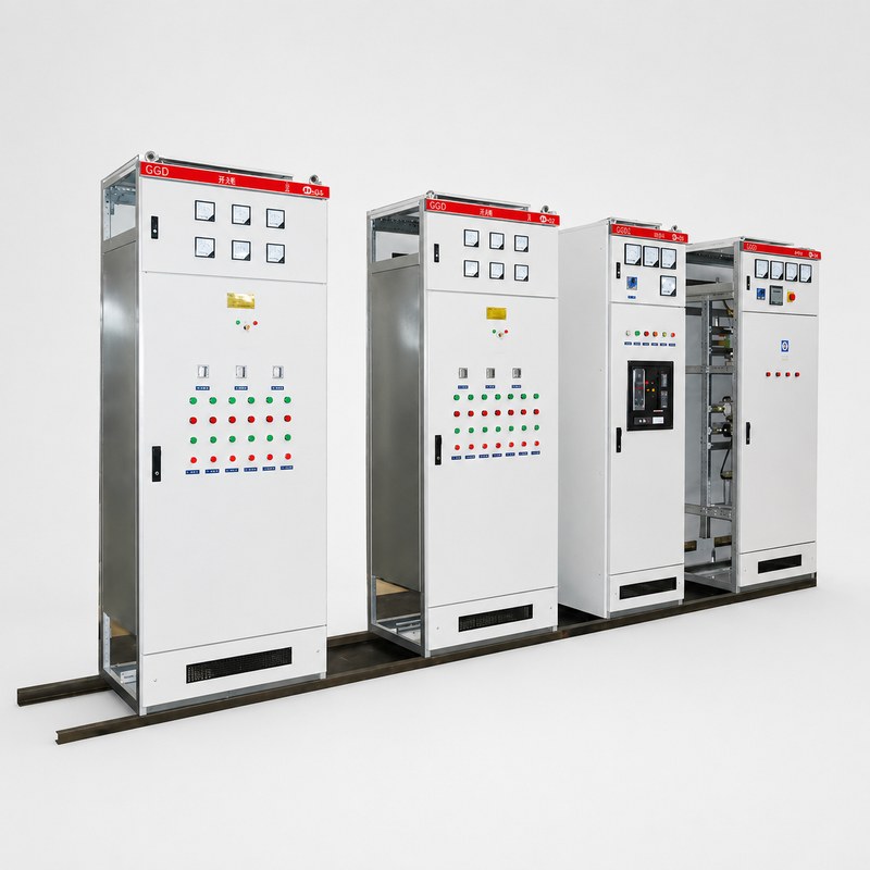
Several engineering principles can significantly improve the long-term performance of an Electrical Distribution Box.
Protective Devices Must Work as a System
Upstream and downstream breakers should not be selected as unrelated components. Their operating characteristics affect which part of the system is disconnected during a fault.
The preferred outcome is usually to isolate the smallest practical section. A branch-circuit fault should not unnecessarily disconnect every load connected to the main box.
Spare Space Has Operational Value
Unused internal space may appear inefficient, but it provides room for safer cable routing, improved heat dissipation, easier maintenance, and future expansion.
A tightly packed enclosure often becomes more difficult to inspect and modify as the system ages.
Circuit Separation Reduces Downtime
Lighting, control systems, process equipment, auxiliary devices, and critical loads should be separated according to operating requirements.
When unrelated loads share one circuit, a single equipment problem may interrupt several functions at once.
Labels Are Part of the Safety System
A circuit label is not merely an administrative detail. It helps operators and technicians understand which loads will be affected before a breaker is opened.
Labels should be specific, durable, readable, and consistent with the latest wiring documentation.
Small Components Can Determine Overall Reliability
Major components often receive the most attention, but small details frequently become the weakest point in the system.
A loose terminal, unsuitable gland, damaged seal, undersized neutral, missing grounding link, or poorly supported conductor can limit the reliability of the complete assembly.
Design Should Reflect Real Operating Conditions
A distribution box should not be designed only from theoretical maximum values. The assessment should also consider operating schedules, startup characteristics, environmental temperature, maintenance practices, vibration, contamination, and likely future changes.
Project voltage, connected loads, phase arrangement, enclosure conditions, protection requirements, and circuit quantity form the basis of an accurate technical specification review before the internal configuration is finalized.
Conclusion
An Electrical Distribution Box works by receiving incoming electrical power, transferring it through a main switching and busbar system, and dividing it among separately protected outgoing circuits.
Circuit breakers protect branch conductors and connected loads from abnormal current. Neutral conductors provide a normal return path, while grounding conductors help protective devices respond to insulation failures and energized metal parts.
Reliable operation depends on the complete system rather than one component. Busbar capacity, conductor size, breaker coordination, grounding continuity, connection quality, internal temperature, enclosure protection, cable routing, labeling, and maintenance access must all work together.
A correctly designed Electrical Distribution Box does more than distribute electricity. It creates a structured, maintainable, and protected electrical system that can respond effectively to changing loads, equipment faults, environmental conditions, and future expansion.
FAQ
What does an Electrical Distribution Box do?
An Electrical Distribution Box receives incoming electrical power and divides it into separate circuits. It also contains switching and protective devices that control individual branches, disconnect abnormal currents, and allow parts of the system to be isolated for maintenance.
What happens when a circuit breaker trips?
When a circuit breaker detects an overload, short circuit, or another condition outside its operating limits, it opens the circuit and stops current flow. The underlying cause should be identified before the breaker is reset, particularly when tripping happens repeatedly.
Can one Electrical Distribution Box supply different equipment?
Yes. One box can supply lighting, sockets, motors, controls, machinery, and auxiliary systems through separate outgoing circuits. Each branch must have conductors and protective devices selected according to its load, starting characteristics, and operating environment.
Why is grounding important in an Electrical Distribution Box?
Grounding provides a low-impedance path for fault current when an energized conductor contacts exposed metal. This supports rapid protective-device operation and reduces the risk of accessible conductive parts remaining energized during an insulation failure.
How often should an Electrical Distribution Box be inspected?
Inspection frequency depends on loading, operating duty, environment, equipment age, and maintenance requirements. Systems exposed to dust, moisture, vibration, heat, frequent switching, or heavy continuous loads normally require closer and more regular assessment.