Table of Contents
Introduction
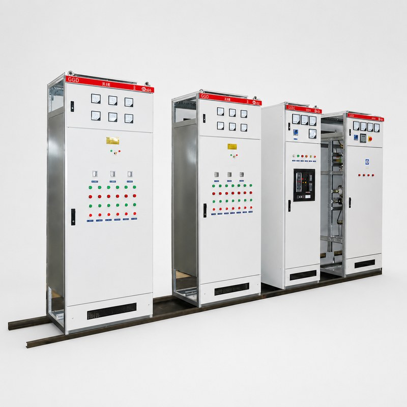
A distribution cabinet inspection checklist helps maintenance teams evaluate whether electrical equipment remains safe, organized, and suitable for continued operation. A power distribution cabinet contains breakers, busbars, conductors, terminals, metering devices, control components, grounding connections, and other parts that can gradually be affected by load changes, temperature, vibration, contamination, loose connections, and repeated operation.
Inspection should not be treated as a quick visual check of whether the cabinet is still energized. Many developing problems do not immediately interrupt power. Loose terminals can create localized heating, ventilation paths can become obstructed, cable identification can become unclear after modifications, and operating loads can gradually move beyond the conditions assumed during the original design.
A practical distribution cabinet inspection checklist should therefore combine visual condition, electrical loading, connection integrity, thermal behavior, protection, cable organization, environmental conditions, documentation, and maintenance history. The following ten checks provide a structured way to evaluate a distribution cabinet throughout its operating life.
1. Inspect the Cabinet Enclosure and External Condition
Begin the inspection before opening the cabinet.
The enclosure protects internal electrical components from accidental contact and from environmental conditions such as dust, moisture, contamination, and physical impact. Damage to the enclosure can therefore affect much more than appearance.
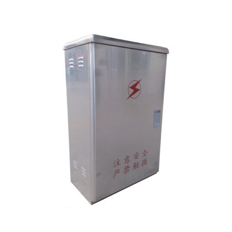
Inspect doors, panels, hinges, locks, seals, ventilation openings, mounting points, and cable-entry areas. Look for deformation, corrosion, damaged coatings, loose fasteners, blocked ventilation openings, or evidence that water or contaminants may be entering the enclosure.
The cabinet should also remain properly positioned. A floor-standing cabinet should be stable and securely mounted, while wall-mounted equipment should remain correctly supported. Unexpected movement or structural distortion can place additional stress on cable connections and internal components.
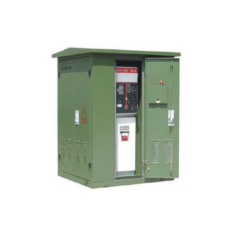
For outdoor or environmentally exposed installations, particular attention should be given to sealing and condensation. Moisture found inside an enclosure does not always mean that rainwater has entered directly. Temperature changes can create internal condensation even when the cabinet appears externally sealed.
The condition of the enclosure should therefore be considered part of electrical reliability rather than a purely mechanical inspection item.
2. Check for Signs of Overheating
Heat is one of the most useful indicators of developing electrical problems.
Busbars, breakers, conductors, terminals, and connection points naturally generate some heat during operation. What matters is whether the temperature pattern remains consistent with the load and equipment design.
Discoloration, damaged insulation, unusual odor, deformed plastic components, darkened terminals, or visible heat damage can indicate that a connection or component requires further investigation.
Overheating can develop for several reasons. A connection may have become loose, a conductor may be carrying more current than expected, ventilation may be restricted, or the cabinet may have accumulated more equipment than its original layout was designed to accommodate.
Temperature should therefore be interpreted together with electrical load.
A heavily loaded feeder will naturally operate differently from a lightly loaded one. The concern is not simply that one component feels warm, but whether its condition differs significantly from comparable components or from previous inspection records.
Where approved maintenance procedures permit thermal inspection, repeated measurements can help identify gradual change before visible damage develops.
3. Verify Breakers and Protective Devices
Protective devices are responsible for limiting the effect of abnormal electrical conditions, so their condition should form a central part of any distribution cabinet inspection checklist.
Inspect circuit breakers and other protective devices for visible damage, loose mounting, contamination, abnormal mechanical condition, or indication that they have operated unexpectedly.
Labels and circuit identification should also remain clear.
A breaker may still appear physically normal even when the connected system has changed. If downstream equipment has been added or feeder loading has increased, the original protection arrangement should be reviewed to confirm that it still matches the actual circuit.
Protection should not be evaluated independently from the rest of the system.
Incoming protection, outgoing breakers, cable capacity, connected loads, and upstream equipment all form part of the same protection hierarchy. Changes made to one part of the system can influence the suitability of another.
The broader principles of electrical safety also reinforce the importance of controlled isolation, suitable protective equipment, and appropriate maintenance procedures around energized electrical systems.
Inspection personnel should follow the site’s approved electrical safety procedures before accessing internal cabinet components.
4. Inspect Busbars and Main Electrical Connections
Busbars carry power through the main distribution path of the cabinet, making their condition especially important.
Where inspection procedures allow safe access, check visible busbar sections, supports, joints, insulation, and connection areas for signs of discoloration, contamination, mechanical movement, damaged insulation, or overheating.
Connections deserve particular attention because electrical resistance can increase when a joint becomes loose or deteriorates. Higher resistance can create localized heating, which may gradually damage surrounding materials.
However, visual inspection alone does not prove that every connection is satisfactory.
Maintenance procedures may include additional checks according to the equipment design, operating condition, and site rules. Any tightening or intervention should follow appropriate technical procedures rather than applying arbitrary force to electrical connections.
Busbar supports should also remain secure. Mechanical forces can occur during abnormal electrical events, and physical support is important for maintaining conductor spacing and alignment.
A cabinet that has experienced a significant fault should therefore receive more detailed evaluation than one undergoing a routine visual inspection.
5. Review Incoming and Outgoing Cable Connections
Cable terminations connect the cabinet to the rest of the electrical distribution system.
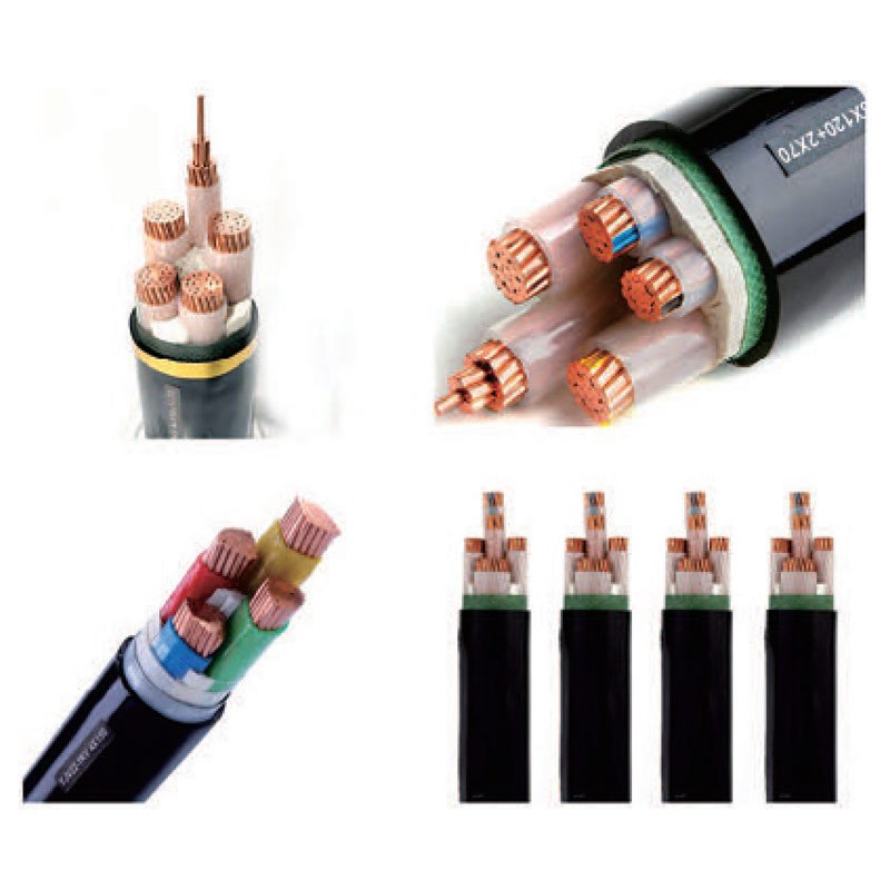
Inspect incoming and outgoing conductors for visible insulation damage, abnormal bends, loose support, discoloration, contamination, or mechanical stress near termination points.
Cable lugs and terminals should remain aligned and organized. Conductors should not place unnecessary mechanical force on breakers, busbars, or terminal blocks.
Cable identification is equally important.
Every outgoing feeder should be traceable to the equipment or downstream distribution point it supplies. If modifications have been made but labels were not updated, future troubleshooting can become unnecessarily difficult.
Cable-entry areas should also remain properly managed. Unused openings should not compromise enclosure protection, while newly added cables should not interfere with existing conductors or ventilation paths.
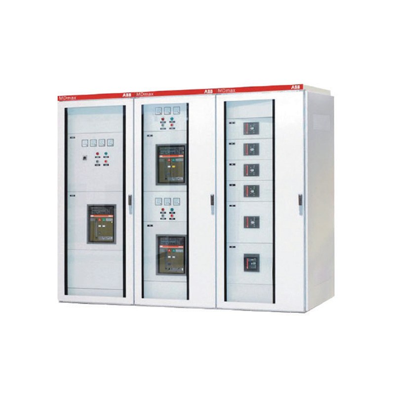
The power distribution cabinet category includes different cabinet configurations for low-voltage distribution and integrated applications, but regardless of cabinet type, cable entry and termination space should remain organized throughout the equipment lifecycle.
6. Check Grounding and Bonding Connections
Grounding and bonding connections are easy to overlook because they normally carry little or no operating current, yet they become essential under abnormal conditions.
The cabinet enclosure, doors where required, internal conductive parts, and grounding conductors should remain connected according to the electrical design.
Inspect visible grounding points for loose hardware, corrosion, damaged conductors, contamination, or modifications that may have affected continuity.
Particular attention should be given to equipment that has been modified.
Adding a new door, panel, cable gland, internal mounting plate, or downstream circuit can change the physical arrangement of the cabinet. Maintenance teams should confirm that these modifications have not unintentionally interrupted the intended grounding path.
Grounding conductors should also remain clearly identifiable and should not be mixed unnecessarily with unrelated control wiring.
The purpose of this inspection is not simply to confirm that a grounding conductor exists. It is to confirm that the intended conductive path remains mechanically secure and consistent with the current cabinet configuration.
7. Compare Actual Loading with the Original Design
One of the most important inspection tasks is comparing current operation with the cabinet’s intended design.
Distribution systems change over time. New machines may be connected, production equipment may operate for longer periods, additional downstream cabinets may be installed, and circuits may be reassigned.
These changes can gradually increase the load on incoming feeders, busbars, and outgoing circuits.
Review available current measurements, load records, and feeder information where monitoring is available. Look for circuits operating close to their intended capacity or phases that are significantly more heavily loaded than others.
Load imbalance deserves attention because it can affect conductor loading and the overall operating condition of the system.
The inspection should also look beyond total cabinet current.
A cabinet can operate within its overall capacity while one individual feeder is heavily loaded. Conversely, several spare breaker positions do not necessarily mean additional electrical load can be added safely.
Physical spare space and electrical spare capacity are different.
The upstream source, incoming feeder, busbars, protection devices, cables, and thermal conditions all need to support additional demand before a new circuit is introduced.
8. Inspect Ventilation, Dust, and Internal Cleanliness
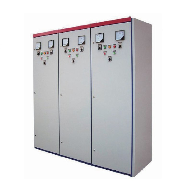
Electrical cabinets need an environment suitable for their internal components.
Dust can accumulate on horizontal surfaces, ventilation openings, insulation, breakers, and other components. In some environments, contamination can interfere with heat dissipation or contribute to insulation problems.
Ventilation openings should therefore remain clear.
If filters or designed airflow paths are present, their condition should be reviewed according to the cabinet’s maintenance requirements. Equipment added after commissioning should not block the intended circulation of air.
Internal cleanliness should also be evaluated in relation to the installation environment.
A cabinet located in a clean electrical room may require a different inspection frequency from equipment operating near production processes that generate dust or contamination.
Cleaning procedures must be appropriate for electrical equipment. Maintenance teams should avoid introducing moisture, conductive contamination, or mechanical damage while attempting to improve cleanliness.
Repeated contamination can also indicate that the cabinet environment itself needs attention rather than simply more frequent cleaning.
9. Confirm Metering, Indicators, and Control Functions
Meters, indicators, alarms, and control devices help operators understand the condition of the electrical system.
During inspection, verify whether displays appear normal and whether indication matches the actual operating state of the cabinet.
If a breaker is open, the corresponding status indication should not suggest that the feeder remains energized. If alarms are available, maintenance records should show whether repeated alarms have been investigated rather than simply reset.
Meters can also support load assessment.
Current, voltage, energy, power factor, or other available measurements can help identify changes that are not visible during a physical inspection.
The objective is not simply to confirm that every display is illuminated. It is to determine whether monitoring information remains useful and consistent with actual cabinet operation.
Control functions should also be reviewed if the cabinet includes automatic or remote operation.
Maintenance teams should understand which functions can operate automatically, which require local control, and whether the current operating mode matches the intended system strategy.
10. Review Labels, Drawings, and Maintenance Records
Documentation is one of the most frequently neglected parts of cabinet maintenance.
A distribution cabinet can remain electrically functional while its labels and drawings gradually become inaccurate after years of modifications.
Every significant change should therefore be reflected in the relevant documentation.
Check whether feeder labels match actual downstream circuits. Confirm whether the single-line diagram still represents the installed system. Verify that circuit schedules, equipment identification, and maintenance records correspond to the current cabinet arrangement.
Maintenance history can also reveal patterns.
Repeated overheating at the same connection, recurring breaker operation, frequent contamination, or recurring abnormal load conditions should not be treated as unrelated events.
Trend information can help identify an underlying system issue that may not be obvious from a single inspection.
Accurate documentation also reduces maintenance time. Technicians can understand the cabinet more quickly when the physical arrangement, circuit labels, and electrical drawings tell the same story.
Distribution Cabinet Inspection Checklist
The following table can be used as a practical inspection framework.
| Inspection Area | What to Check | Warning Signs |
|---|---|---|
| Enclosure | Doors, seals, mounting, corrosion, openings | Damage, moisture, loose panels |
| Temperature | Breakers, busbars, terminals, cables | Discoloration, odor, abnormal heat |
| Protection | Breakers and protective devices | Damage, repeated operation, incorrect labeling |
| Busbars | Supports, joints, insulation | Loose parts, contamination, heat damage |
| Cables | Terminations, support, insulation, identification | Loose connections, stress, damaged insulation |
| Grounding | Conductors and bonding points | Corrosion, loose or missing connections |
| Loading | Incoming and outgoing circuit demand | Overloaded feeders, severe imbalance |
| Ventilation | Openings, airflow, internal cleanliness | Blockage, dust accumulation |
| Monitoring | Meters, alarms, indicators, controls | Incorrect status, recurring alarms |
| Documentation | Labels, diagrams, maintenance history | Outdated drawings or unclear circuits |
The value of a distribution cabinet inspection checklist comes from reviewing these items together rather than treating them as isolated tasks. For example, abnormal heat may be connected to increased load, a loose connection, blocked ventilation, or a combination of several factors.
How Often Should a Distribution Cabinet Be Inspected?
There is no useful universal interval that fits every distribution cabinet.
Inspection frequency should reflect operating conditions, equipment criticality, loading, installation environment, maintenance history, and site procedures.
A cabinet operating in a clean electrical room with stable loading may require a different maintenance schedule from equipment exposed to dust, moisture, vibration, high temperature, or frequent load changes.
Equipment supporting important production or infrastructure systems may also justify closer monitoring because the operational impact of an electrical failure is greater.
Inspection frequency should therefore be risk-based.
Routine visual checks can identify obvious changes, while more detailed planned inspections can review internal condition, electrical loading, connections, protection, and documentation according to approved maintenance procedures.
Records from previous inspections can help refine the schedule. If a particular cabinet repeatedly develops contamination, abnormal heating, or loose connections, maintenance frequency should reflect that actual experience.
Why Thermal Inspection Can Reveal Hidden Problems
Many developing electrical faults create heat before they create a complete circuit failure.
A loose connection increases resistance. Increased resistance can generate additional heat. Over time, that heat can damage insulation, terminals, nearby components, or the connection itself.
This makes temperature comparison useful in preventive maintenance.
The strongest information often comes from patterns rather than one isolated temperature value. Similar phases and comparable feeders can provide useful references, while historical records can show whether one connection is becoming progressively warmer under similar load conditions.
Load must always be considered.
A heavily loaded circuit should not be compared directly with a lightly loaded circuit without understanding the difference in current.
Thermal information should therefore be combined with electrical measurements, physical inspection, and maintenance history.
The objective is not simply to find the warmest component. It is to identify temperature behavior that does not match the expected operating condition.
How Load Changes Affect Cabinet Inspection
Many power distribution cabinets operate for years after their original commissioning, while the facility around them continues to change.
This creates a maintenance challenge.
A cabinet originally designed for one group of loads may eventually supply additional equipment. Individual circuits may be modified, operating hours can increase, and spare positions may gradually become occupied.
The electrical system should therefore be periodically compared with the original design assumptions.
The site’s low-voltage equipment is intended to support organized distribution, protection, control, and maintenance within the broader system architecture. When the distribution structure changes significantly, the cabinet should be reviewed as part of the complete upstream and downstream system rather than evaluated only from its physical condition.
This is particularly important before adding large new loads.
The fact that an unused breaker position exists does not prove that the cabinet has sufficient electrical capacity.
What Should Be Checked After a Cabinet Modification?
Any significant modification should trigger a targeted inspection.
If a new feeder is installed, maintenance personnel should confirm conductor routing, terminal condition, protective-device selection, circuit identification, and the impact on total cabinet loading.
If protective devices are changed, coordination with upstream and downstream equipment should be reviewed.
If new monitoring or control equipment is added, wiring should remain organized and should not obstruct access to existing components.
Cabinet modifications can also affect heat distribution.
Adding several devices to a previously open section changes component density and can influence internal airflow.
Documentation should be updated immediately after the work is completed rather than waiting for the next scheduled maintenance period.
A cabinet is easiest to maintain when its physical configuration and documentation evolve together.
Common Distribution Cabinet Inspection Mistakes
One common mistake is inspecting only the visible front of the cabinet.
Meters and breaker handles can appear normal while cable terminations, busbar joints, or internal wiring show signs of deterioration. A complete inspection needs to consider the parts of the cabinet that actually carry and distribute electrical power, while following appropriate isolation and safety procedures.
Another mistake is focusing only on whether equipment is damaged.
Inspection should also identify change. A feeder drawing more current than during previous inspections may indicate growing demand even when no damage is visible.
Ignoring documentation is another frequent weakness. Incorrect labels increase troubleshooting time and can make future modifications more difficult.
Cleaning without investigating why contamination repeatedly returns can also treat the symptom rather than the cause.
Finally, maintenance teams should avoid assuming that every spare circuit position represents usable capacity. Expansion decisions require review of the complete low-voltage distribution system, including source capacity, busbars, cables, protection, and thermal conditions.
How Inspection Supports Preventive Maintenance
Inspection becomes much more useful when it contributes to preventive maintenance rather than functioning only as a compliance task.
A single inspection provides a snapshot. Repeated inspections create a history.
That history can show whether load is gradually increasing, whether one connection repeatedly develops abnormal temperature, whether contamination accumulates faster than expected, or whether a particular protective device operates more frequently than comparable circuits.
Trend information helps maintenance teams prioritize work.
Instead of waiting for a component to fail completely, developing conditions can be investigated while the cabinet remains part of a planned maintenance program.
This is especially important in electrical distribution because small problems can affect multiple downstream loads if they occur at a central cabinet.
Preventive maintenance therefore depends on consistency. Inspection methods, records, feeder identification, and measurement practices should remain sufficiently standardized that results from different maintenance periods can be compared meaningfully.
A Four-Stage Inspection Method
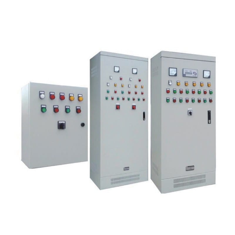
A practical distribution cabinet inspection can be organized into four stages.
The first stage is external assessment. Inspect the enclosure, surrounding environment, mounting condition, ventilation, cable-entry points, and visible evidence of abnormal operation.
The second stage is electrical-condition review. Evaluate loading, breaker status, monitoring information, signs of overheating, and any recent abnormal events recorded by operators.
The third stage is detailed internal inspection according to approved isolation and safety procedures. Review busbars, conductors, terminals, grounding, protective devices, control components, and cable organization.
The final stage is documentation and follow-up. Record findings, compare them with previous inspections, update circuit information where necessary, and identify any condition requiring further testing, repair, or engineering review.
This method turns inspection into a repeatable process rather than an informal visual check.
Conclusion
A distribution cabinet inspection checklist should help maintenance teams understand how the equipment is changing over time, not simply confirm that it is still operating.
A complete inspection should review enclosure condition, overheating, protective devices, busbars, cable terminations, grounding, electrical loading, ventilation, monitoring, and documentation. These areas interact with one another, so an abnormal condition should rarely be evaluated in isolation.
Load growth deserves particular attention because electrical systems frequently change after commissioning. Spare physical space does not necessarily mean spare electrical capacity, and additional circuits can affect busbar loading, protection, cable organization, and thermal conditions.
Inspection records are equally important. Comparing current findings with previous conditions can reveal developing problems before they become obvious failures.
A structured distribution cabinet inspection checklist therefore supports safer maintenance, clearer troubleshooting, better expansion decisions, and more reliable long-term operation of the power distribution system.
FAQ
What should be included in a distribution cabinet inspection checklist?
A distribution cabinet inspection checklist should cover enclosure condition, breakers, busbars, cable terminations, grounding, loading, overheating, ventilation, meters, alarms, labels, drawings, and maintenance records. Findings should be compared with previous inspections whenever possible.
How often should a power distribution cabinet be inspected?
Inspection frequency should reflect cabinet loading, environmental conditions, equipment criticality, maintenance history, operating changes, and site procedures. Equipment exposed to demanding environments or supplying important loads may require more frequent attention than lightly loaded cabinets in controlled rooms.
What are common signs of a distribution cabinet problem?
Warning signs can include unusual odor, discoloration, abnormal heat, repeated breaker operation, loose connections, damaged insulation, excessive dust, moisture, corrosion, abnormal meter readings, unclear labels, or significant differences between actual loading and the original design.
Why should cable connections be checked during cabinet inspection?
Cable terminations carry current between the cabinet and the wider electrical system. Loose, damaged, contaminated, or mechanically stressed connections can create resistance and localized heating. Cable identification and routing should also remain clear so maintenance and troubleshooting stay manageable.
Can spare breaker positions always be used for new loads?
No. Empty positions indicate physical space, not guaranteed electrical capacity. Before adding a new load, the incoming supply, busbar rating, feeder capacity, protection, cables, fault conditions, thermal performance, and upstream distribution system should all be reviewed.
Need Help Reviewing Your Power Distribution Cabinet?
If your project requires a new cabinet configuration or an existing distribution system needs to accommodate additional loads, feeder changes, or updated operating requirements, contact our technical team with your single-line diagram, load information, cable arrangement, and installation conditions for configuration support.